Welcome to our site! EDAboard.com is an international Electronics Discussion Forum focused on EDA software, circuits, schematics, books, theory, papers, asic, pld, 8051, DSP, Network, RF, Analog Design, PCB, Service Manuals... and a whole lot more! To participate you need to register. Registration is free. Click here to register now.
@Jonathan.. I can see you have no formal design training on how to specify inputs, processes and outputs.
There is a methodology for doing this for logic design such as this. I suggest you read up on it.
It starts with a table format of all your switch inputs and and LED outputs and has a present state and next state.
From that a Karnaugh Map is created.
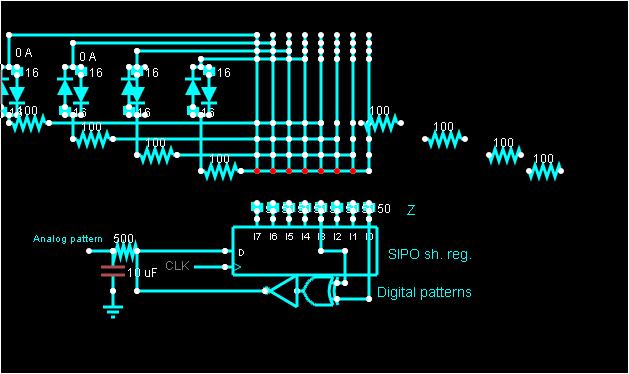
This can be done for both binary and 3 level logic as Tr-state or open circuit or both drivers at same level. (0 or 1)
We dont concern ourselves yet with how to implement it, but we know it is possible to drive bipolar LEDs in 3 states direct from a PIC. But since you do not know what is possible, let me give you a heads up.
3 states = i.e. Output = High, Low; Off (Both ports equal 1 or 0 or either port=input).
The driver impedance for a 5V PIC (LV CMOS logic) is around 50 Ohms. this is the internal RdsON for these types of MOSFETs, so Vol, Voh current can be estimated using Ohm's Law and diode threshold voltage. for each colour and determine what series R is needed if any. Naturally, ESR rises with very low currents and with differential drive, you now have 2x50 Ohms in series plus LED Vth, which is the Forward voltage, Vf at 20mA minus IR drop (16 Ohms*20mA=320mV, for almost all 20mA LEDs.
Since ESR is a quality parameter, it has a wide tolerance (like hFE in transistors) which is the primary cause for variations in Vf at 20mA. But at 1~2mA , all the same colours have exactly the same voltage from different vendors.
Since you will be driving these at lower currents, This will work well.
High Bright LEDs are in the 1~30 Candella [Cd] range depending on focus angle as opposed to ancient std LED indicators that were 10~300 millicandella [mcd] approx. which also had different chemistry and lower threshold voltage.
The best colors to match for sharing current with equal brightness and Iv rating will have similar threshold voltages @ 2mA are RED/YELLOW/ORANGE (Vth~1.8). Due to Nitrate content BLUE/GREEN/WHITE are Vth(2mA) ~2.8V (NOT Vf ~20mA)
With millions of LEDs to choose from, with search skiils, you can match intensity sharing a common series R with the info I have shared above., ( You wont find these secrets anywhere else)
This site uses cookies to help personalise content, tailor your experience and to keep you logged in if you register.
By continuing to use this site, you are consenting to our use of cookies.