Continue to Site

Welcome to EDAboard.com

Welcome to our site! EDAboard.com is an international Electronics Discussion Forum focused on EDA software, circuits, schematics, books, theory, papers, asic, pld, 8051, DSP, Network, RF, Analog Design, PCB, Service Manuals... and a whole lot more! To participate you need to register. Registration is free. Click here to register now.

P-channal or N-channal

Status
Not open for further replies.

naseerak

Full Member level 5
Joined
Jun 14, 2003
Messages
241
Helped
19
Reputation
38
Reaction score
19
Trophy points
1,298
Activity points
1,222
I am designing a pwm solar charge controller but having difficulty in choosing mosfets, my design is for 24v system with 42v solar pannal if I use p-channal then it is easy to measure current as the ground are common but in the case of n-channal I don,t want to use high side drivers due to complexities and cost but with simple drive I have to switch the grounds which will avoid me using current measurements any thoughts are welcome here, Presently I have IRF4905 and a lot of other n-channal power mosfets.
 

Use smart power switches. They not so expensive, but replaces a lot of descrete elemets.
 

I would think this is a simple buck application since you
have such a panel voltage surplus. It seems to me that
you should be able to find half-bridge schemes with low
side current sensing and NMOS totem pole power train
topology. NMOS always wins on performance per cost,
and a bit of design effort ought to amortize away pretty
quick if this is more than a one-off.

Depending on battery particulars, you might find a do-all
IC solution and even if not, plenty of reference designs to
pick from and scale up.
 

Using a simple PWM on off control does not offer maximum power transfer from PV which normally starts around 80% Voc and moves lower several% with less than rated solar input.

Whereas a continuous intermediate voltage buck converter with cap on input and output will regulate ideal MMPT and secondary buck down converter from here. If this is new territory for you, then read up on it.

The simpler way is a single stage MMPS chip using one stage to regulate PV loading voltage near 80% or by tracking Peak power using MMPT algorithm and independently regulating output current in CC mode, CV or float CV mode when lightly loaded.

It depends on your load profile and source power profile, storage capacity and overall desired efficiency, considering battery charging efficiency might only be 50% or higher depending battery quality.

High power systems are starting to use magnetic float bearing flywheels in a vacuum for storage at greater energy storage efficiency.

- - - Updated - - -

Use smart power switches. They not so expensive, but replaces a lot of descrete elemets.

Good point.

student ought to become aware of smart switches used everywhere in automotive apps, with protection of temp, OVP , OCP and reverse V .

- - - Updated - - -

If your Panel is 24V at rated power , I would consider 24V batteries then you only need OVP at 14-14.2V
 

    V

    Points: 2
    Helpful Answer Positive Rating
I don,t want mppt for now but just a simple pwm regulator and want to measure the current. please suggest a working schematic for driving Nmos or Pmos
 

Topic regarding solar panels is very popular last time. To obtain maximum efficency, mcu based pwm controllers used. They 'looking for' optimal point on U/V chart with specific alghorithm.
 

I don,t want mppt for now but just a simple pwm regulator and want to measure the current. please suggest a working schematic for driving Nmos or Pmos

Either way works with differential input and 50 mV current shunt.

For high volume, both cost , RdsOn are important . So choose what matches your needs.

Now you can choose better solutions in perfect designs or try to copy.

http://cds.linear.com/docs/en/datasheet/6106fa.pdf
 

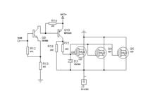
I am using Hall effect sensors so the position of the mosfets are irrelevant here. look at this schematic and suggest me to proceed.


I am using Hall effect sensors so the position of the mosfets are irrelevant here. look at this schematic and suggest me to proceed.


PWM should be aplied between R12 and R13. But this is only the switch. PWM here is useless. Looks like you are absolutly have no any knowledges about that what you a trying to realize.
 

Status
Not open for further replies.

Similar threads

Part and Inventory Search

Welcome to EDABoard.com

Sponsor

Back
Top