Continue to Site

Welcome to EDAboard.com

Welcome to our site! EDAboard.com is an international Electronics Discussion Forum focused on EDA software, circuits, schematics, books, theory, papers, asic, pld, 8051, DSP, Network, RF, Analog Design, PCB, Service Manuals... and a whole lot more! To participate you need to register. Registration is free. Click here to register now.

overvoltage protection in inverter voltage sensing

Status
Not open for further replies.

AssemblyLine

Member level 1
Member level 1
Joined
Nov 1, 2013
Messages
35
Helped
0
Reputation
0
Reaction score
1
Trophy points
1,288
Activity points
1,608
I am working on 3 phaseAC machine inverter.
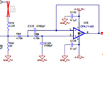
For measuring the motor phase voltages I use the following circuit
voltage.PNG

In my project the op-amps supply voltage is +/-5VDC; the inverter module supply voltage is +15VDC. These power supplies are deried from an isolated +5VDC supply. So the op-amps and the inverter module (which contains the power igbts) are not isolated one from each other. The GND_PH from the above picture is connected to the DC intermediary stage of the inverter.

In the scenario in which one of the resistor from the voltage divider would fail open ( R76, R87, R94) I would have very high voltages to the op-amp inputs (U22). Those bidirectional diodes (D37, D38) are there to prevent that, by clamping those high voltages to about 2-6 V (from diodes 's datasheet).
voltage.PNG

Question :
1.If i want to use the configuration in which unipolar voltage is sensed (by using R75 and just the OPA211), in order to have overvoltage protection should I put those diodes like that? Also should I put those diodes on the GND line too?
2. What would be the errors introduced by those diodes in the signal I want to measure? All I could think is the leakage current of diodes. But I don't know how that would affect the divided voltage
3. If I want to use varistors instead of TVS what would be the errors introduced?
 
Last edited:

Hi,

At this position the voltage is limited to +/-5 before.
The diodes are useless.

Klaus
 

It is limited only at the input of the first op-amp. If I am going to use R75 , there will be this voltage divider which will feed the second op-amp. Now the inputs of this second op-amp are not clamped.
When using R75(namely the second voltage divider, the output of the first op-amp is disconnected by not putting R85 resistor).
So this logic follow my question: should I put clamping diodes for the second divider?
 

Hi,

The first Opamp is supplied with +/-5V...therefore the output always is lower ...

Again: no need for clamping diodes. They will never become active.

Klaus
 

In the scenario in which one of the resistor from the voltage divider would fail open ( R76, R87, R94) I would have very high voltages to the op-amp inputs (U22). Those bidirectional diodes (D37, D38) are there to prevent that, by clamping those high voltages to about 2-6 V (from diodes 's datasheet).

Most OPs have an input clamping feature with limited current capability, e.g. 5 to 10 mA. In so far external clamping diodes are usually not required. Another question is why you're arbitrarily picking off less likely failure cases.

I also don't understand the relation of the different +/-5V supply nodes.

My personal favorite is omitting the various OPs and dual supplies and feeding the SD converter directly from input voltage divider. You must however provide a common offset voltage to comply with the input voltage range.
 

That schematic can be used with the first op-amp and SD converter, with both op-amps and SD converter, with the second op-amp and SD converter, and just with the SD converter.
I want to test all configurations , using the same board by putting or not some 0R resistors
For the first op-amp, namely the following schematic
first op amp.png
if the voltage divider wil fail open , those diodes wil clamp the high volltages to +/-5V

Iff Im using the second op-amp and the SD converter, of course first op-amp will not be used. And I am doing that by not putting R85 on the PCB
second op amp.png
So the second voltage divider will be effective (the one not between 2 phases , but between phase and ground).
So I'm thinking that the second op-amp must be protected as the first , having clamping diodes on the op-amp input (U23)
The purpose of those op-amps are buffering and filtering the divided voltage.

It does not matter if the op-amp is supplied from +/-5V, if higher than absolute maximum voltage is applied on the inputs (with no current limit), my op-amp will be bricked. The diodes are preventing that
 

It does not matter if the op-amp is supplied from +/-5V, if higher than absolute maximum voltage is applied on the inputs (with no current limit), my op-amp will be bricked. The diodes are preventing that
As said, they aren't required. Review datasheets, particularly the input protection paragraph.

DESD1P0RFW leakage current is relative high, even exceeding OPA211 input current at elevated temperatures, and IN826 input current in any case. If at all, you would use low leakage clamping diodes in this place.

I should add, that this are minor reservations and points that can be fixed when evaluating circuit operation. The overall design doesn't look bad.

A special point that should catch your attention is the rating of voltage divider resistors. Check if they are suited for the intended working voltage.
 

Yes, the op-amps have internal protection diodes but I would not want to blow them because the chip would be useless then, that is why I want to use external diodes which has higher rating power.

The resistors are standard SMD 1206 which have 200V rating.

I don't fully understand the relationship between the diodes leakage current and op-amp input current. Why should I worry? Could you please explain more?

- - - Updated - - -

Also I have another question related to those ESD diodes. How can be the clamping voltage (2-8V) smaller than the reverse working voltage (70V) ?
 

Status
Not open for further replies.

Similar threads

Part and Inventory Search

Welcome to EDABoard.com

Sponsor

Back
Top