soheilpaper
Newbie level 1
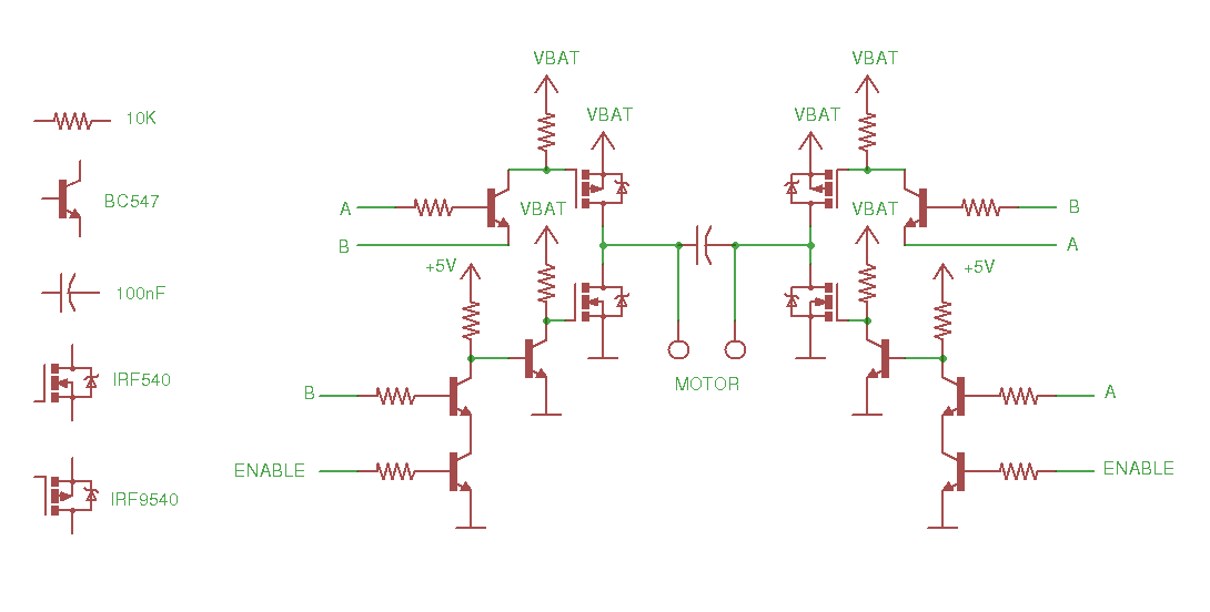
i have done the circuit in the pic :
from :
http://letsmakerobots.com/content/yet-another-fet-based-h-bridge?page=1
so two upper MOSFET (irf9540) will be overcharged and so heating but there is no power output for DC motor (VBat = 12v) and (v-A or V_B=12v)
so what do you think?!.
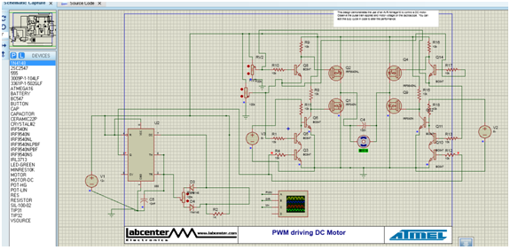
i simulated this circ in Proteus (combined with an IC555 for PWM and you could see its image in :

But it don't working in simulation too. in simulation the irf540 with or without enable and A & B input how 65mV as Vgs! my be if i change its biasing part it work.
And i how another Question :
What would be happended if i will drive a MOSFET with nominal Vgs (like 10V) and how no load in its drain .is it overheating!?
i think its don't work correctly in biasing of irf540 MOSFETs . so could you help me to make it correct.
Thanks a lot.
from :
http://letsmakerobots.com/content/yet-another-fet-based-h-bridge?page=1
so two upper MOSFET (irf9540) will be overcharged and so heating but there is no power output for DC motor (VBat = 12v) and (v-A or V_B=12v)
so what do you think?!.
i simulated this circ in Proteus (combined with an IC555 for PWM and you could see its image in :
But it don't working in simulation too. in simulation the irf540 with or without enable and A & B input how 65mV as Vgs! my be if i change its biasing part it work.
And i how another Question :
What would be happended if i will drive a MOSFET with nominal Vgs (like 10V) and how no load in its drain .is it overheating!?
i think its don't work correctly in biasing of irf540 MOSFETs . so could you help me to make it correct.
Thanks a lot.
Last edited by a moderator: