digi001
Full Member level 5
I am looking to latch an enable signal only when my fpga is addressed correctly and recieves a specific code. But i am having issues getting this to work. Is my code correct?
Here is my verilog:
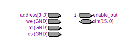
module fpga_enable_version(xint,cs,rd,we,address,enable_o ut);
input cs;
input rd;
input we;
input [3:0]address;
output enable_out;
inout [15:0]xint;
reg enable_reg;
initial
begin
enable_reg=1'b0;
end
assign enable_out = enable_reg;
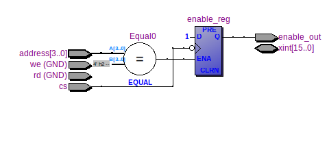
always @ (*)
begin
if (address==4'b0010 && cs==0 && we==0 && xint==16'b0000111100001111)
begin
enable_reg <= 1;
end
end
endmodule
Here is my verilog:
module fpga_enable_version(xint,cs,rd,we,address,enable_o ut);
input cs;
input rd;
input we;
input [3:0]address;
output enable_out;
inout [15:0]xint;
reg enable_reg;
initial
begin
enable_reg=1'b0;
end
assign enable_out = enable_reg;
always @ (*)
begin
if (address==4'b0010 && cs==0 && we==0 && xint==16'b0000111100001111)
begin
enable_reg <= 1;
end
end
endmodule
")