Continue to Site

Welcome to EDAboard.com

Welcome to our site! EDAboard.com is an international Electronics Discussion Forum focused on EDA software, circuits, schematics, books, theory, papers, asic, pld, 8051, DSP, Network, RF, Analog Design, PCB, Service Manuals... and a whole lot more! To participate you need to register. Registration is free. Click here to register now.

Output/input resistance with negative feedback

Status
Not open for further replies.

webald0

Newbie level 6
Newbie level 6
Joined
Mar 7, 2013
Messages
14
Helped
0
Reputation
0
Reaction score
0
Trophy points
1,281
Visit site
Activity points
1,408
I am trying to calculate output and input resistance of this AB class amp: SEMA U MCU.jpg
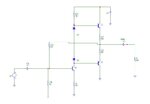
I calculated R input in this way: Rin=(hie1+hfe*R3)||(R2)||R1/(Av+1)

hie1=324,67ohm, hfe=130

I have measured it and the result is very similar, but my mentor says there is another way (more propriet) for calculating it

And also, i have measured Output resistance but i dont have a clue how to calculate it because of negative feedback.

Without NFB it would be R4||R5||RT i suppose..

Measured output resistance is 4.33ohm with 8ohm load resistor

Measured input resistance is 284ohm.

Thank you for your time and help!
 

In the way that you have connected the input, there is no feedback: in the small signal analysis, all the independent voltage source will be grounded as a result the base node of Q1 will be shorted to ground and therefore, there is no feedback :).

The output impedance in this case will be approx. (R4+re2)||(R4+re3)+R6/(2*beta). If you take into account the load resistance (usually people do not do that), it will be (R4+re2)||(R4+re3)+R6/(2*beta)||Rl.
 
  • Like
Reactions: webald0 and FvM

    FvM

    Points: 2
    Helpful Answer Positive Rating

    webald0

    Points: 2
    Helpful Answer Positive Rating
Thank you very much on your reply. I still dont understand it very well but ok.. I thought there is feedback because R1 goes from output to input.
 

Thank you very much on your reply. I still dont understand it very well but ok.. I thought there is feedback because R1 goes from output to input.
It would if the signal source has some resistance. But an ideal source has zero resistance so any negative feedback voltage is absorbed by the source and shunted to ground.
 
Thanks for replies. Can you guys give me a formula for Input resistance please?
 

of an amplifier. I assume it would be Rin=R1||R2. But result is very different from measurements. Rin measured is 284 ohm.

Also, Rout measured is 4.33ohm with 8.2ohm load so the formula in first reply is missing something or i am reading it wrong because the result is about 500ohm which is far from the measurements..

I need this calculations because i am doing this amplifier for my final exam. I did all measurements but i am very bad with calculations, i dont understand few things so this is why i am asking all this..

sorry for my bad english
 

In fact your original input resistance in post #1 is correct, although you didn't tell the assumed Av value. There's apparently a misunderstanding. Milad-D explained why the output resistance isn't affected by feedback over R1. The input resistance however is. For an exact Av calculation, you also need to know Q2/Q3 current gain.

You also didn't yet tell your Rout calculation.
 
  • Like
Reactions: LvW

    LvW

    Points: 2
    Helpful Answer Positive Rating
In fact your original input resistance in post #1 is correct, although you didn't tell the assumed Av value. There's apparently a misunderstanding. Milad-D explained why the output resistance isn't affected by feedback over R1. The input resistance however is. For an exact Av calculation, you also need to know Q2/Q3 current gain.

You also didn't yet tell your Rout calculation.

Av=10

Thank you people for helping me to solve this!
 

Status
Not open for further replies.

Part and Inventory Search

Welcome to EDABoard.com

Sponsor

Back
Top