Continue to Site

Welcome to EDAboard.com

Welcome to our site! EDAboard.com is an international Electronics Discussion Forum focused on EDA software, circuits, schematics, books, theory, papers, asic, pld, 8051, DSP, Network, RF, Analog Design, PCB, Service Manuals... and a whole lot more! To participate you need to register. Registration is free. Click here to register now.

OTA design problem current not stabilizing

Status
Not open for further replies.

styxies

Junior Member level 1
Joined
Aug 30, 2018
Messages
16
Helped
0
Reputation
0
Reaction score
0
Trophy points
1
Activity points
109
Hi, I am trying to design a pseudo-differential transconductor, but the output current is not stabilizing for larger values of Vin(differential) which results to a warped Gm vs Vin(differential) plot.

What could be the problem?

snapshot.png

From the upper plot is the Gm vs Vin plot, while the lower plot is the current out.

The common mode of the input used is at 1V, anyother common mode value used will lead to a more warped Gm vs Vin(differential) plot.
 

Post schematic please. It would be more effective.
 

Post schematic please. It would be more effective.

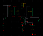
I am sorry, here is the schematic with the test bench I am using. The test bench contains pad and esd parasitics since this is for tapeout.

snapshot1.png


snapshot2.png
 
Last edited:

hello, can you please elaborate?
 

How is the x-axis? Did you sweep Vin from negative region to positive or from 0V to something?
 

M37 and M38 why different? There are too much asymmetries, quite overcomplicated diff.pair.
 

M37 and M38 why different? There are too much asymmetries, quite overcomplicated diff.pair.

I actually tried with the both of them as the same, and the result was the same as well.

I am told that this isn't actually a problem since when designing OTAs the goal is to keep the Gm relatively constant for a range of inputs, but I would need a textbook or journal citation to back this statement up, which I don't have.
 

... when designing OTAs the goal is to keep the Gm relatively constant for a range of inputs, but I would need a textbook or journal citation to back this statement up, which I don't have.

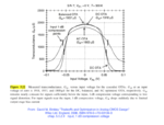
Search e.g. Binkley's book for "constant gm". Here's a figure from this book which shows several OTAs' usable input voltage dependency on transconductance:

Transconductance_vs_Input_voltage__Binkley_p.469.png
 

Hi all, the problem was fixed by changing the testbench.

Basically, I had a wrong testbench as my inputs were not totally differential. I needed to have a VCVS with negative 1 gain on my negative input terminal to balance it out.
 

Thanks you shared the final solution, many people don't do that. It was clear that some asymmetry caused the behavior, but from the drawing it was hard to see for me. Just an advice, improve the drawing.
 

Any reference paper of this diff pairs? Thanks.
 

Status
Not open for further replies.

Part and Inventory Search

Welcome to EDABoard.com

Sponsor

Back
Top