Continue to Site

Welcome to EDAboard.com

Welcome to our site! EDAboard.com is an international Electronics Discussion Forum focused on EDA software, circuits, schematics, books, theory, papers, asic, pld, 8051, DSP, Network, RF, Analog Design, PCB, Service Manuals... and a whole lot more! To participate you need to register. Registration is free. Click here to register now.

Oscilloscope GOS-3110 not displaying right

Status
Not open for further replies.

Windmiller

Member level 4
Joined
Mar 30, 2010
Messages
76
Helped
1
Reputation
2
Reaction score
1
Trophy points
1,288
Location
Sweden
Activity points
1,997
Hello!

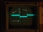
I bought myself an oscilloscop in secondhand and it was a GOS-3110 which I do belive is the same as the NRI-2500. It is a 10Mhz oscilloscope, and when I tested it the first time everything seemed ok with the wave in the middle of the screen. But as the time went on doing some test measurements the wave started slowly to descend until it was off screen, and I tried to bring it back by turning the vertical pot but nothing happend. Even if I turn it off and on, the wave is still far beyond off screen which I can see if I turn the V nob to 5mV and give it more input then I can see the top part of the wave.

From the beginning I was using my homemade 1X probe, made from schematics on this site.. How to Build Your Own Oscilloscope Probes and this was working at first but slowly descending and to not work anymore soo I went over to direct input the lineout from the computer with some music.

I've tried to connect music line out to the input of the oscilloscope, and I can see the top of the wave once again. But not able to bring the wave upp on screen.

What could it be? There's no more nobs to turn, and I've ran out of options because I can't find anything similar on the web, and no manual. I've just found the schematic over the NIL-2500 which should be the same?

When nothing's connected to the darn thing, the wave is not present in screen.. still believe it's off screen even then though I can't see it, because there's no wave then!

Can someone please guide me in this? It's my second time in life that I'm using an oscilloscope, soo please bear with me.

Regards

/ Morgan

Here it is...

oscill2g.jpg
 
Last edited:

Hmmm I've been wondering a bit here, could it not be that the electrolytic capacitors have been dried out after all these years? :/
 

Ah I'm talking to myself, I'll give up.. the vertical POT and V.Var POT is totally dead unable to calibrate it then, I've found the trimmers inside to turn and made the line centered but the waveform is now corrupt after fiddling with all trimmers I could find before I found how to do it right on the web, now it looks ugly. Must have a working v.position and v.variable POT to callibrate, so I will use the box as a bookstand in the shelf and go back to something worth doing.
 

Don't give up yet.

The trace is roughly in the center when the voltages on the Y deflector plates is equal. For the trace to move, something has made one plate higher in voltage than the other. The position control is there to manually adjust the deflector plate voltages and the preset is to set the center point in the mid position of the manual control.

If it is the same as the NRI-2500, first check the 170V supply to the Y deflector amplifiers is correct then check the +9V and -9V supplies, they should be within about 0.2V of 9V, if either is out, the fault lies in the regulator section around Q101 and Q102.

Brian.

Hi Brian!

Thanks for your reply.
Aah, I found Q101 and Q102, but I can't find neither 170V or the 9V supplies.. I'm not that good :/ I'll do my best, thanks alot Brian.. we will see if I can locate them..

By the way, what is the purpose with the vert DC balance trim.. I found it on the backside of the circuit also before?

Regards

/ Morgan
 
Last edited:

Measuring with the negative side of a voltmeter connected to chassis:
Look for R112, one side of it is the regulated +15V supply, the other is the regulated +9V supply.
The equivalent for the negative rails is each side of R113.
If you can find R114, one side should be +350V, the other side is the 170V rail. R114 will be one of the larger sized resistors.

Be very careful, the high voltage supply to the tube is 1170V and it WILL hurt if you touch it!

There are several controls, including vertical balance that are there to make sure the vertical (signal) amplifier can swing equally to each side of zero. If you imagine a worst case scenario, you could have the trace in the middle of the screen, looking perfect, but the amplifier hard against the stops in one direction with the vertical position pulling it back again. The controls balance the amplifier voltages to make sure that with no signal, the trace is a close to the center without compensating more than absolutely necessary. It isn't difficult to set up again but you must fix the problem before trying to calibrate it.

Brian.
 

Hello again..

R112 resistor was displaying 9.5V and on the other side 15.9V
R113 resistor was displaying -9.4V and on the other side -16.2V
So I believe this is fine.. but..
R114 resistor was displaying 202V and on the other side 228V hmm

And I'm still alive :)

/ Morgan
 

The schematic I have is ambiguous, it has an arrow pointing to the higher voltage side of R114 marked 350V but it might be the rating of a capacitor nearby. I wouldn't worry too much with the voltages you saw, if they were missing it would indicate a fault but as there isn't anything that can make them higher it just means they are out of tolerance.

Next checks:
1. find J202, it is a connector with wires going to the tube base. Set the vertical position control in roughly mid position and tell me the voltages on the two pins. These go straight to the Y deflector plates so hopefully they have similar voltages on them.
2. try moving the vertical position control from end to end and let me know if the voltages on the pins of J202 change as the control is turned.
3. measure the voltages on R218 and R219, there should be little difference from one end of each resistor to the other and they should both have approximately the same voltages on them.

Brian.
 

1. J202 is showing 54V in mid pos
2. It displays 54V in every case, no matter how far or in what direction I'm turning the Vertical position POT.
3. When measuring negative side of a voltmeter connected to chassis and positive + to the R218 I did get 0.3V and 0.48V on R219

I didn't see any difference on sides on R218, and I could only measure one side on R219.. because I couldn't reach the other side of it.

Regards

/ Morgan
 

This is good, we are getting closer to the fault.
What SHOULD happen is the vertical position control alters the voltage on the pins of J202. Turned one way, the voltage on one pin of J202 should rise and the other should fall. Turned the other way, the voltages on the two pins should go the other way around. In mid position, they should be approximately equal. The fault is in the vertical deflection amplifier.

Next checks:
Look on your schematics at the area around Q207 to Q212, you will notice the top line (Q207, Q209 and Q211) is mirrored in the bottom line. With the vertical position control mid-way, the voltages on the parts in the top line should be the same as the equivalent parts in the bottom line. You should find that turning the control makes the voltages on one increase while at the same time the other decreases.

As you have already discovered the output of these stages (at J202) does not change when the control is turned, the fault must lies between the control itself (VR205) and J202. Start by checking the voltages match at Q207 and Q208 and work your way toward Q211 and Q212 stage by stage.

Brian.
 
Hey Brian!

Thanks, I've lernt alot from you.. :)

I did my measurments like you said, and everything seems fine according to what you have said, and I measured between/and around R230 and R231 precise at the spot where the VR205 is connnected.. while turning, I didn't get any difference on the voltmeter. I decided to take the VR205 out of the box, and mesure the resistance which clearly showed me nothing, it's completely dead.. soo I guess we found the faulty circuit and it was the VR205 itself.

I believe I must find a new linear 50k POT then.

Regards

/ Morgan
 
Last edited:

Well done - You are now an expert in oscilloscope repairs !
Make sure you get a linear pot and not the kind used for volume controls which have logarithmic tracks. If you use a log one, the control will have almost no effect over most of it's rotation and it will be difficult to adjust.

When you have fitted the new control, move it to center position then adjust VR207 until the trace is on the center line of the screen, you shouldn't need to adjust anything else.

Brian.
 

Thank you :D

Yes, I will get the linear not for the audio.. I'll have that in mind.
By the way, the VR203 Variable 2kB POT was out too.. I will have to get one of those too then.

And one more thing, do you believe it is dangerous for the equipment to be turned on without the VR203 variable POT? Because I just did that while it was out. :/

Thanks again, now I'll order 2 new POTs :)

/ Morgan
 

I don't think any damage will occur if VR203 is broken but obviously it needs to be replaced for normal operation again. VR203 just controls the amount of signal reaching the Y amplifier.

Let me know how you get on with the new controls fitted.

Brian.
 

Hello again..

All of them are now changed to new ones, seems to be working.. but now I need to calibrate it, because the wave is still ugly when testing against the 0.25V cal output pin.
 

What ever I do, I'll get this when the 0.25V CAL pin is to the input!??
It should be inverted, not like on the picture.. and whatever I do it stays the same, miles long tails?

attachment.php


Regards

/ Morgan
 

Attachments

  • why.jpg
    why.jpg
    30.4 KB · Views: 396

Hi Morgan.

Well done getting it working again. The spikes are "overshoot" and it is usually caused by the high frequency response being excessive. Are you using a proper oscilloscope probe and if so is it a divide by 10 type?

If you have a probe and you are not sure if it divides or not, try measuring resistance between the tip and the center pin of the BNC plug. If it is very low resistance it is a straight through (x1) type, if it measures around 1M Ohms it is probably a divide by ten probe (x10). The x1/x10 refers to the way it increases the volts per division on the screen, in reality it does it by dividing the signal by the same amount.
If the probe is x10, you will probably see a small adjustment screw on it's side, with the scope showing the waveform like it is in your photograph, adjust the screw until the spike levels off. If you adjust it too far the rising and falling edges become rounded instead of spiked.

Brian.
 

Hello

Thanks :)

It's a 10Kohm 1x homemade probe made with guidelines from this page: How to Build Your Own Oscilloscope Probes

But I didn't use it when I took the picture, just direct input. I've used it now and it was alot better result, still not great though :)
I wanted to build the 10x probe at this page, but started with the 1x because it seemed easier to build at that moment.

Morgan
 
Last edited:

I'm surprised that such a crude probe was used with such a nice oscilloscope. I have two Tektronix scopes, a 2465 and a 2232 but using a probe like that would ruin their readings. If you look at professional probes you would see they have an additional component, a small adjustable capacitor across the input resistor. This is to allow a little more HF through the input resistor so it counter-acts the effect of the scope's input capacitance and the cable capacitance which together reduce the HF response.

What I suggest you do is connect your x1 probe directly to the calibrator output. Set the volts/division control to give a square wave about two squares high.
Now note the position of VR206 (back in the deflection amplifier again). Try adjusting it to remove the spike, if it doesn't work, return the control to its original position.

If that didn't fix it, I would be inclined to replace C406 (100uF/25V) before going any further. It across the supply to the calibrator oscillator and if you are going to rely on using it to adjust anything I would like to be sure it is producing as clean a signal as possible.

Brian.
 

Agree with you on that it is a crude probe, so I've just ordered a 100Mhz switchable probe between 1x and 10x.. Hope this is a good workable choice?

Anyhow, I got rid of the spikes with my homemade probe, looks much better with the 0.25V CAL now but I can't get it higher than half a square high and down so that the sum is something around 1 square in height no matter how much I turn anything like it is in the previous included picture and this is driving me crazy. This was with the 50mV setting on the oscilloscope, like it should be at a rough calibration according to the manual I found for another GOS-310 oscilloscope.

Thanks, again Brian

/ Morgan
 
Last edited:

Status
Not open for further replies.

Part and Inventory Search

Welcome to EDABoard.com

Sponsor

Back
Top