Welcome to our site! EDAboard.com is an international Electronics Discussion Forum focused on EDA software, circuits, schematics, books, theory, papers, asic, pld, 8051, DSP, Network, RF, Analog Design, PCB, Service Manuals... and a whole lot more! To participate you need to register. Registration is free. Click here to register now.
Hi, is there some option to make DAC from just open-collector outputs? A common R2R ladder is probably not possible since it is not able to supply a full current through collector resistor.
Thx, 4bit resolution (16 levels). 5% accuracy is enough. It’s just for generating a waveform close to sine-wave as a reference for pwm to drive small motor.
just feed the openCollector signals (pullup´d) to a digital buffer, a level converter, a push-pull driver, a MUX ... just to get "constant impedance" as FvM states.
just feed the openCollector signals (pullup´d) to a digital buffer, a level converter, a push-pull driver, a MUX ... just to get "constant impedance" as FvM states.
If you mean open-collector TTL, those are not very accurate.
Classic R2R DACs fed by steered current sources look like
open collector (or open drain JFET) but the tail current is
firmly controlled by common feedback. Such a DAC needs
to be pushing current into a virtual ground summing junction
(comparator w/ VIN+ = 0 for a SAR ADC assembly, op amp
w/ VIN+ = 0 for a voltage mode output (various precision
resistors and references in supporting roles).
If you want a simple binary DAC for a PWM, consider just
a weighted resistor set driven bang-bang by a set of high
current (low Ron) CMOS outputs. Maybe give this DAC-
cobble its own clean VDD. You can make the output lower-Z
and center it by a couple more divider resistors if (say)
you want the range centered and limited consistent with
the PWM function's modulating input. 1/0 weight symmetry
is best against a VDD/2 summing junction.
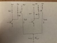
I am not sure how to connect the weighted resistors. But I have an idea to enable 4 current sources (1,2,4,8mA) by these open-collectors and supply some resistor. It should be pretty linear, isn’t it?
The question seems to be about a DAC where current moves one direction only. This simulation has a weighted resistor network and diodes, driven from a 4-bit counter. The resulting output ramp has curvature which is sine-like.
--- Updated ---
Click link below to run this simulation on your computer:
1) Navigates to Falstad.com/circuit
2) Loads my schematic in the animated interactive simulator
3) Runs on your computer
This site uses cookies to help personalise content, tailor your experience and to keep you logged in if you register.
By continuing to use this site, you are consenting to our use of cookies.