Continue to Site

Welcome to EDAboard.com

Welcome to our site! EDAboard.com is an international Electronics Discussion Forum focused on EDA software, circuits, schematics, books, theory, papers, asic, pld, 8051, DSP, Network, RF, Analog Design, PCB, Service Manuals... and a whole lot more! To participate you need to register. Registration is free. Click here to register now.

Opamp UGB

Status
Not open for further replies.

fpmkh0

Newbie level 6
Joined
Apr 18, 2021
Messages
11
Helped
0
Reputation
0
Reaction score
0
Trophy points
1
Activity points
118
Hi,
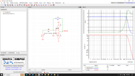
I have a basic question. If I want to implement a filter (first order) using opamp, I wrap a parallel RC around the opamp as shown below. Let's say I want to have a gain of 0dB (RF=RI). If I have a healthy phase margin, does it matter if my UGB is very close to my BW of interest for my filter? In another word, why do people say UGB must be much larger than the desired BW? Except for phase margin, what else do I need to look for? For example, if my UGB is 200MHz and my filter BW is 160MHz, while my phase margin is 60 degrees, is there anything that I need to look for? What is the potential issue with having a UGB so close to my filter BW? Thank you.

1669661712868.png
 

You'll look for the actual filter transfer function. In principle, the exact transfer function is at least second order due to the effect of OP open loop gain, in so far different from the first order transfer function of the ideal active filter with infinite OP gain. Also the cut off frequency will be shifted.

Suggest to simulate the actual transfer function for different OP bandwidth to answer the question yourself.
 

OpAmps in this frequency range are very demanding to keep
stable. Take a look at this and its user guide and datasheet.


You also have to deal with, usually, at least a two pole G response,
and thats not including poles of parasitics.

Don't underestimate effectiveness of caps at these frequencies, especially for
bypass. My experience was to use a network analyzer in 1 50 ohm environment
and actually test various vendors caps for esr behaviour. You would be amazed at folks
who sell the same cap, same V, same datasheet, same everything and what you actually
find in circuit behavior.


Regards, Dana.
 
Last edited:

fpm, I think a couple of points aren't clear here. Pls confirm my assumptions:
* UGB here is unity-gain bandwidth of your opamp with the feedback broken (i.e. open loop, but still providing an equivalent loading to your opamp)
* your labels state PGA (programmable gain amp?), but it's probably just a regular opamp?
* you measured phase margin with your RC filter configuration as shown?

Assuming the above is correct, for your filter to function, you want your opamp to be in high gain at all times, such that opamp's inputs are virtually shorted (to each other). It is only in that case you can consider the loop closed, and per the inverting amplifier topology that you have Vout=I_Rinput*Z_RCfeedback, where Z_RCfb will have your single RC pole.

If your f_input_signal=UGB_opamp_openLoop=f1
@ f1: G_openLoop_amp=1
=> Vin_amp(+)-Vin_amp(-)=Vout_amp(+)-Vout_amp(-)
in which case the filter's transfer function is broken and the output is ill defined.
Generally speaking all circuits based on feedback around an opamp, rely on the fact that the Gain_opamp = very large, in the bandwidth of interest. I think that's why the advice you found requires UGBW to be >> than operational bandwidth of your filter.
 

A fun exercise is to model a simple opamp with a single pole, inverting,
and do a s plane analysis solving for :

1) Zin
'2) Zout
3) Virtual ground

You can see as you run out of G the virtual ground starts to disappear, Zout
starts looking inductive, Zin capacitive. You can even establish, use PFE on the
expressions, the values of effective L and C at a given frequency.

Here you can see that behavior. As you can see it would affect any complex filter
behavior, like as in this sim where the single pole rolloff of G affected Zin and Zout.
here you can see Virtual ground disappearing, Zin falling, Zout rising......

1671274092248.png


Regards, Dana.
 

Attachments

  • 1671273504703.png
    1671273504703.png
    116 KB · Views: 89
Last edited:

In addition to the above -excellent- suggestions, also consider that nonlinear distortion, psrr and cmrr are directly related to the difference between open and closed loop gain ('excess gain'). Depending on your application, the lack of excess gain may cause problems in the higher frequency range.

Also the internal opamp poles in general have some drift and part to part tolerances (+/-10%?). If you don't limit the closed loop bandwidth enough, the spread of these poles will be visible when comparing part to part. So for designs that will be replicated I take it as good practice to have the external R/C's dominate the AC behaviour.
 

Status
Not open for further replies.

Similar threads

Part and Inventory Search

Welcome to EDABoard.com

Sponsor

Back
Top