Continue to Site

Welcome to EDAboard.com

Welcome to our site! EDAboard.com is an international Electronics Discussion Forum focused on EDA software, circuits, schematics, books, theory, papers, asic, pld, 8051, DSP, Network, RF, Analog Design, PCB, Service Manuals... and a whole lot more! To participate you need to register. Registration is free. Click here to register now.

Opamp integrator practical circuit

Status
Not open for further replies.
the maths behind the AC frequency response

H(s) = -1/Ts

(T = integrator time constant)

What's your problem, how the circuit achieves this transfer function, or what the transfer function (pole in the origin) means?
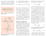
 

The equation (9) in the screenshot below relates to the lossy integrator. However, if you plot the given Vout/Vin transfer function, it gives totally different frequency response compared to the wikipedia image.

Screenshot from 2018-07-03 15-53-53.png
 

Hi,

However, if you plot the given Vout/Vin transfer function, it gives totally different frequency response compared to the wikipedia image.
I assume you plotted the frequency response already.
It would be very kind of you to upload your results.

Klaus
 

However, if you plot the given Vout/Vin transfer function, it gives totally different frequency response compared to the wikipedia image.
Sounds unlikely. Show the response you are getting.
 

Hi,

one problem is that your integrator circuit has inverting character. Thus the output is negative.
The other problem I see is that your scales are linear instead of logarithmic.

Mind: the "db" scale seems to be "linear" but indeed the "logarithmic" function is already in the dB calculation.

I assume your X-Axis shows the frequency: Here you go to negative frequencies. This is not useful.

I can´t see where the used component values come from. Do they make sense? I assume not, but I did not verify it.

Klaus
 

Make sure you understand exactly what a bode plot is.

It tells you a specific thing: "How does my circuit behave over time", in a specific way: by measuring the response to different sine wave inputs. The in time domain high frequency -> short times, low frequency -> long times.

So specifically even if you put 10uV into an ideal integrator the output is going to go up and keep going up forever. The gain is only limited by how long you wait. This is exactly what the slope of the bode plot represents where it gets higher as frequency goes down (longer 'wait' times).

On the other hand with RF present the gain will be be limited to RF/R1 under any circumstance. If that ratio is 10,000 then a 10uV input will approach 0.1V and stop. And that's what the other line of the wikipedia curve represents.
 

See the updated equation using log function
Another useless plot. Start reproducing the axis units step by step. Notice that both magnitude and frequency are logarithmic.
 

Hi,

Within this time of discussion you easily could have downloaded LTspice and drawn and simulated your circuit with it.

Klaus
 

The math error you're making is that S is a complex number. You don't substitute X for S, you substitute jw for S which can be called ix where i is imaginary and x is radians.

The bode plot is now the plot of the real and the imaginary parts of that function. I'm rusty on wolfram alpha but here is a quick take:

RC filter with RC=1: 1/(s+1) -> 1/(jw+1) -> 1/(ix+1):
https://www.wolframalpha.com/input/?i=plot+1/(ix+1)

Massaging into a log plot (there is a better way to do this):
https://www.wolframalpha.com/input/?i=plot+[log((1/(i*(10^x)+1))),+{x,+-2,+2}]

The second one appears be in correct bode plot form and therefore shows the general path from S domain function to getting a magnitude and phase plot. Again, LTSpice is better at doing this with the circuit directly.
 

Status
Not open for further replies.

Similar threads

Part and Inventory Search

Welcome to EDABoard.com

Sponsor

Back
Top