Continue to Site

Welcome to EDAboard.com

Welcome to our site! EDAboard.com is an international Electronics Discussion Forum focused on EDA software, circuits, schematics, books, theory, papers, asic, pld, 8051, DSP, Network, RF, Analog Design, PCB, Service Manuals... and a whole lot more! To participate you need to register. Registration is free. Click here to register now.

Opamp configuration large signal and small signal

Status
Not open for further replies.

parkpika

Junior Member level 3
Joined
Jun 18, 2013
Messages
26
Helped
0
Reputation
0
Reaction score
0
Trophy points
1
Location
parkpika
Activity points
183
Opamp configuration

I have a very basic question about opamps. Say we have an integrator, using R and C.
integrator.PNG

The equivalent model for the opamp is,
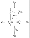
diff pair.PNG

If I take the second figure and add R and C and ground one of the diff pair, does it still function as an integrator? If so, do people just use the first picture because it is easier to see?

Is it implied that Vo in the first picture is Vo1-Vo2?
 
Last edited:

You equivalent model is a differential stage, not an opamp. It is not equivalent since it has a differential output and the opamp has a single ended output. You need to add a differential to single-ended stage, such as this, to your model to convert Vo1-Vo2 to the single-ended output to more closely model the opamp. You also need additional functions such as a level shifter stage and compensation to fully model the op amp.
 

Re: Opamp configuration

The equivalent model for the opamp is,
No, they're not equivalent. The opamp in the first picture will typically have much higher gain than you can achieve with the second circuit, and it only has one output. Also, in the second circuit the output voltages cannot go more than about 0.5V below the input voltages.

That said, you could make an integrator with the second circuit, but not a very good one. To do that, take the output from the collector of Q1. Q2's collector can be connected directly to Vcc.

(oops - cross post with Zapper. :/)
 

The most important differences between both circuits are
* the gain (opamp: 1E5...1E6; diff. stage: 10...100), and
* the output impedance (opamp: 50...100 ohms; diff.stage: kohm range).
* input impedance (opamp: Megohm range; diff. stage: kOhm range)

(The differential output of the diff. stage would not create any problems; there are operational amplifiers having also two outputs with different polarity)

Please note that the first circuit can act as an integrator only because the opamp can be treated as a (nearly) ideal unit:
Very large open-loop gain with very large input resistance and rather low output impedance.
 

Does the opamp have more gain simply because it has a diff pair and a cascaded CS stage?

If I were to take an 741 opamp and drew R and C appropriately for a integrator and ground one of the input, it would be the same as the first picture right?
 

Does the opamp have more gain simply because it has a diff pair and a cascaded CS stage?
If I were to take an 741 opamp and drew R and C appropriately for a integrator and ground one of the input, it would be the same as the first picture right?

Each opamp has some internal stages providing the required gain (1E5...1E6) and an output stage providing the low output resistance.
Yes - of course you can use the 741 type as shown in the 1st circuit. But be aware that you cannot test this circuit as it is because non-ideal properties of the amplifier (offset voltage) will charge the capacitor and prevent linear operation (integration). Practical integrator stages have a resistor Rp in parallel to the capacitor (Rp~100..1000 times the input R) .
 

Status
Not open for further replies.

Similar threads

Part and Inventory Search

Welcome to EDABoard.com

Sponsor

Back
Top