Welcome to our site! EDAboard.com is an international Electronics Discussion Forum focused on EDA software, circuits, schematics, books, theory, papers, asic, pld, 8051, DSP, Network, RF, Analog Design, PCB, Service Manuals... and a whole lot more! To participate you need to register. Registration is free. Click here to register now.
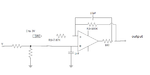
Are sure about the connection of the 10pF capacitor?
Normally, such an additional feedback capacitor is connected directly at the opamp output.
In this case, the additional resistor (RT=100 ohms) can stabilize the amplifier circuit against heavy capacitive load impedances CL.
The principle is as follows: The resistor RT=100 ohms forms - together with a load capacitance CL (not shown in the circuit) - a passive lowpass. The influence of the corresponding pole frequency can be (partly) compensated by a zero created by a highpass capacitor CF (10pF in your case). Both RC combinations together can be seen as a frequency-compensated voltage divider (known from the oscilloscope probe).
For this purpose, it is necessary to make k*CL(r,out+RT)=CF(r,out+R2) with r,out=opamp open-loop output resistance and k~1.3
This site uses cookies to help personalise content, tailor your experience and to keep you logged in if you register.
By continuing to use this site, you are consenting to our use of cookies.