juz_ad
Full Member level 2

- Joined
- Dec 17, 2011
- Messages
- 130
- Helped
- 0
- Reputation
- 0
- Reaction score
- 0
- Trophy points
- 1,296
- Activity points
- 2,541
I'm hoping someone can take a quick look at this and double-check my assumptions.
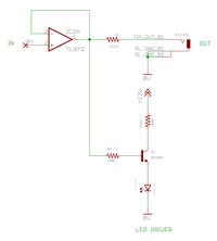
Standard op-amp buffer as output. Input is from 'in-circuit', output is to the outside world.
Is the impedance of the jack output still 1K even though there is an LED driver also hanging off the same op-amp output?
Any real reason why not to do this under 'normal' use?
<Edit 1> Input signals are 0V or +10V only - it's an output for a logic device. No negative or AC signals.
Thanks!
J
Last edited:
