vleam13
Member level 1
Hi,
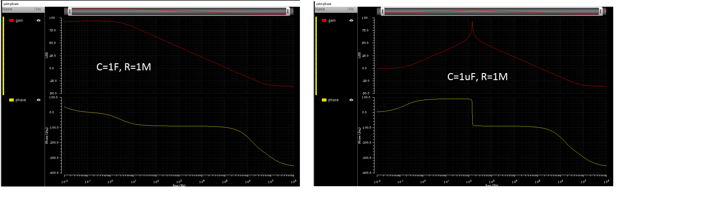
Usually I use large resistor (>1M ohm) to break the loop between output/ inverting input (feedback path) of op-amp. Large Capacitor also added (1F) at inverting input.
AC + DC level source added at non-inverting input to run simulation. Output over Non inverting input used for gain/phase calculation.
from my understanding. Big resistor used to break the loop because we cannot leave it open, we need DC operating point. Big Capacitor to allowed AC signal pass over.
Please correct me if I am wrong.
Question:
1) what is the different if I put AC + DC source at inverting (between big capacitor and ground) or non-inverting input.
2) What is the consideration to set capacitor and resistor value? How to decide the optimized value?
3) why sometime we replace big resistor with big inductor?
Thanks.
regards.