Continue to Site

Welcome to EDAboard.com

Welcome to our site! EDAboard.com is an international Electronics Discussion Forum focused on EDA software, circuits, schematics, books, theory, papers, asic, pld, 8051, DSP, Network, RF, Analog Design, PCB, Service Manuals... and a whole lot more! To participate you need to register. Registration is free. Click here to register now.

Occillators which use transformers - not simulating in LTSpice

Status
Not open for further replies.

Weylin

Newbie level 6
Joined
Sep 19, 2012
Messages
14
Helped
0
Reputation
0
Reaction score
0
Trophy points
1,281
Activity points
1,408
Hello, first post here, so I apologize if this is the wrong section, or if this has been resolved before (Google searches didn't lead me to any possible solutions, or I don't know the right key words)


I was trying out some of the circuits from my old electronic project labs, the kind with the little spring terminals, such as this one "**broken link removed**"

The circuit in particular I'm trying is on page 15 on the right side of that PDF.


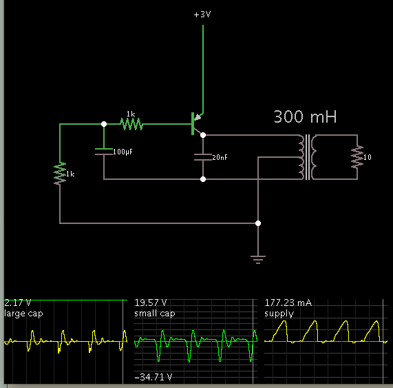
I'm trying to simulate this in LTSpice, but it's not oscillating like it should. That, or this type of circuit simply doesn't work with 'perfect' models, or there is some aspect of the circuit that is not being simulated.

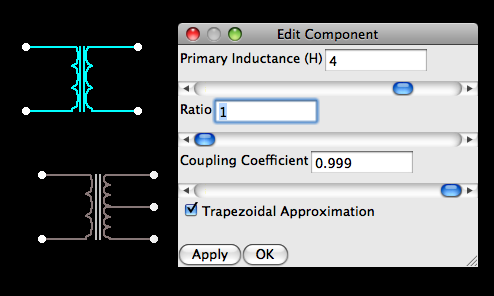
Here's an image of what I have, I'm not entirely sure what inductance the transformer should have, or if I even did that part properly, because the transformer is key to this oscillator functioning.

2zylzld.png


full size image: https://i50.tinypic.com/2h55rwi.png
 

Hi, I got this to oscillate in a simulator.

I started out with the same values from your schematic.

I found I had to play with the henry value of the transformer. Between 300 mH and 1 H is suitable.

I found I had to reduce the 100k to more like 1k. After a while the large capacitor acquires over 2 V, and starts to turn off the PNP transistor. Oscillations become sporadic. I found a 1k value maintains oscillations by preventing the base from rising too high.

The small capacitor seems to contribute a ringing effect between the main pulses. Did the book call this a 'squegging' oscillator, by any chance?

Here is my schematic, with scope traces:

 
How is your transformer modeled?
LTSpice doesn't have any transformers by default, and I'm not sure if "K1 L1 L2 L3 1" is correct, or if I need to possibly set that last number to something else.

I tried changing the last value to 0.95 and it works, with frequency lowering the lower I make the K1 number.
I'm not entirely sure what it does though, is it how well the coils are coupled, with 1 being an impossibly perfect transformer?


EDIT: I'm also having trouble with the .wave out function, the wave form basically loses a LOT of resolution in the process of being saved as a .wav so ends up losing the 'ringing' that was evident in the graph
 
Last edited:

There is a perfect stable DC solution which won't oscillate in
transient. But real parts have noise that destabilizes the thing
and then it will ring up. Put a 1nA, 1nS kicker pulse into the
base and see what happens.
 

I'll contradict the somewhat general claim in the post title. There are two problems involved with the original circuit:

- it's not oscillating with an 1:1:1 transformer because the load impedance is cancelling the positive feedback action. 1:1:0.5 (in terms of inductance) will already work.
- after changing the transformer ratio or increasing the load resistance, it's oscillating with about 10 s period, so you won't see the oscillation in 5 sec analysis time

After respective corrections the circuit is starting to oscillate in LTSpice without any "kick-start" impulse, even with the originally applied supply ramping. Otherwise skipping initial transient solution ("uic" flag) would be sufficient to make it work.
 
  • Like
Reactions: LvW

    LvW

    Points: 2
    Helpful Answer Positive Rating
R2=100k and C2=100uF are values quite horribles for that oscillator. With R2=1k works "fine"
 

R2=100k and C2=100uF are values quite horribles for that oscillator.
True. Nevertheless it's apparently used by the "Electronic Playground" kit. If it's not a typo, they are producing very slow clicks instead of tones.

The transformer can be expected to provide at least 10:1 impedance ratio, as needed for impedance matching in a low power audio output stage. In so far the circuit with work somehow.
 

The circuit was for some 'grandfather clock'
Not that it tells time, it just had an approximate 1 second delay on clicks.


I remember getting some interesting characteristics from some of my sets oscillators, the ones that did a frequency shift would very often 'slip' into the next octive. instead of ramp up smoothly.

Thank you all for the help thus far :grin:

I think that more or less resolves the problems I was having, but I'll need to do more experimentation.
 

How is your transformer modeled?
LTSpice doesn't have any transformers by default, and I'm not sure if "K1 L1 L2 L3 1" is correct, or if I need to possibly set that last number to something else.

I tried changing the last value to 0.95 and it works, with frequency lowering the lower I make the K1 number.
I'm not entirely sure what it does though, is it how well the coils are coupled, with 1 being an impossibly perfect transformer?

How unexpected to hear that LTSpice lacks a transformer, yet it often gets mentioned favorably at this board.

I am using Falstad's interactive animated simulator.

www.falstad.com/circuit

It has a transformer and tapped transformer.

Screenshot of edit window:

3513348400_1348171342.png


The tapped type has only inductance and ratio.

Default value is 4 H.

I think coupling coefficient is the number you referred to. The default in Falstad's is .999.

But that raises a question about K1 because reducing the henry value should make oscillations get faster.

This is a link which will load my layout into falstad's simulator and run in on your computer:

https://tinyurl.com/btkllzd

You can change values at will by right-clicking on a component, to bring up an edit window.

EDIT: I'm also having trouble with the .wave out function, the wave form basically loses a LOT of resolution in the process of being saved as a .wav so ends up losing the 'ringing' that was evident in the graph

Don't know how to help here.

I see from the Elenco manual that this oscillator produces clicks every second. The simulator shows the interaction happening onscreen, but it's still up to us to figure out how the coil interacts with two capacitors, to achieve that.
 

How unexpected to hear that LTSpice lacks a transformer, yet it often gets mentioned favorably at this board.
I don't get your point. You're discussing a simple wrapper around the simulator that fills-in some parameters as an essential feature. There are lots of user written macros available if you like it. Much more interesting is that LTSpice provides a full featured saturable core model.

Nevertheless is the implemented circuit not working at 1 Hz, nor does the 100k*100 µF time constant suggest this frequency. There are some differences, e.g. using a 2SA germanium transistor, but it can hardly explain the frequency difference. This is a relaxation oscillator, the frequency isn't set by a LC resonator.
 

True. Nevertheless it's apparently used by the "Electronic Playground" kit. If it's not a typo, they are producing very slow clicks instead of tones.
The transformer can be expected to provide at least 10:1 impedance ratio, as needed for impedance matching in a low power audio output stage. In so far the circuit with work somehow.
Ah,ah... You are right.

That oscillators are very "all dependant", changing the "generic PNP" (is not a good transistor :) ) by any other , works as expected.

**broken link removed**
 
  • Like
Reactions: FvM

    FvM

    Points: 2
    Helpful Answer Positive Rating
I don't get your point. You're discussing a simple wrapper around the simulator that fills-in some parameters as an essential feature. There are lots of user written macros available if you like it. Much more interesting is that LTSpice provides a full featured saturable core model.

Nevertheless is the implemented circuit not working at 1 Hz, nor does the 100k*100 µF time constant suggest this frequency. There are some differences, e.g. using a 2SA germanium transistor, but it can hardly explain the frequency difference. This is a relaxation oscillator, the frequency isn't set by a LC resonator.

I looked and I found transformer constructs in LTSpice's examples folder, including:
Transformer.asc (2 winding)
Transformer2.asc (3 winding)
IdealTransformer.asc
NonLinearTransformer.asc (saturable).

User-adjustable parameters include henry value, peak current, series resistance, parallel R, parallel C. (Same as parameters for an inductor.)

These are sophisticated models. If I were working with transformers every day I think I would look to Spice (in one of its versions) to assist me. Because transformers are among the most difficult of components to understand and use properly.

Nevertheless I would not be the only one who wishes transformers were condensed into one easy-to-use component. Falstad's simulator makes this possible. We can see what's going on. Is there a Spice version that does the same?

If only my simulator (as well as Mr. Falstad's) could be merged with a Spice version. Then we would have accuracy and a large list of devices, combined with animation and ease of interaction.
 

IMHO the intended use of the classical SPICE simulator, including all it's successors like PSpice LTSpice and of the Falstad simulator are different. Although LTspice isn't bad to set up intuitively accessible educational designs, it's primarly a high performant circuit simulator, supporting levelXX MOSFET models, behavioral modelling, Laplace transformation of s-domain representations and other advanced stuff. I won't expect this from the Falstad simulator.

Personally, I don't like the visualization provided with Falstad, but that's a matter of taste. If people are getting insights from the animated charge carriers, or whatever you see in the funny diagrams, it may serve a purpose.
 
  • Like
Reactions: LvW

    LvW

    Points: 2
    Helpful Answer Positive Rating
You can change the current display between conventional and electron, and it does help a lot in visualizing what exactly is going on in a circuit.
Just from looking at the behavior, you can visualize a hydrolic model, such as how a capacitor behaves like a diaphragm, and an inductor resembles a weighted turbine.
If you're new with electronics, that sort of stuff can give you a better idea of what does what.


I found LTSpice to be missing a few things, such as being able to pan the view of the work space, and selecting multiple components at once to easily make changes to a larger schematic.
It's still useful, but I've yet to understand and utilize many of the powerful functions.
 

IMHO the intended use of the classical SPICE simulator, including all it's successors like PSpice LTSpice and of the Falstad simulator are different. Although LTspice isn't bad to set up intuitively accessible educational designs, it's primarly a high performant circuit simulator, supporting levelXX MOSFET models, behavioral modelling, Laplace transformation of s-domain representations and other advanced stuff. I won't expect this from the Falstad simulator.

Personally, I don't like the visualization provided with Falstad, but that's a matter of taste. If people are getting insights from the animated charge carriers, or whatever you see in the funny diagrams, it may serve a purpose.

Yes, I believe many a student of electronics can gain insight from a simulator which features both animation and interaction.

In earlier years I recall looking at schematics in books, especially ones that use a handful of components to do the impossible (example, voltage multipliers). Even when building some of these circuits, I only vaguely grasped what was going on. I wished there could be a way to put a meter on every wire, and then slow down the action, and watch.

I have been doing some more reading about Spice's development. When I got my Macintosh computer in 1991, I downloaded Spice and I tried modeling a circuit by writing a netlist. It was a lot of effort. It made me say to myself 'Computers are supposed to make it easier than this.'

So I have worked for years on a computer program to mimic 'a meter on every wire'. And having gone to the effort, it has put me in a vantage point to appreciate that Falstad accomplished things with his simulator I have not.

So I ought to promote his simulator, the same as I would like to promote mine (the day it's marketable).

However I see that Falstad's has not gained hardly any attention despite its benefits. Nor have a few other animated simulators I've seen. They bring a quality called accessibility to electronics. Yet accessibility 'doesn't get no respect'.

No matter. This seems to be the niche I have sought out for myself at this stage. Its a vast sea, the electronics field. Often we are drawn to one of its sub-categories. One guy might concentrate on radio projects. Another on digital projects. Etc.

The Spice interfaces (wrap-arounds) are a big improvement on the Spice of decades ago. However to get anything done still requires us to go through so many actions. Why is this?

I've found Falstad's gives me greater results in less time. It's streamlined, although it has quirks. (But what simulator doesn't?)

Now, what if we could manage to get access to Spice's algorithm, and run it frame by frame? We could tweak things more easily. Get results on the fly.

Spice and its variants can do 50x what Falstad's can do. But then it has also had several decades to flourish and develop, and gain support among the electronics community. I believe a whole lot of engineers and educators really would like for animation to be added to its list of features.
 

Status
Not open for further replies.

Similar threads

Part and Inventory Search

Welcome to EDABoard.com

Sponsor

Back
Top