Continue to Site

Welcome to EDAboard.com

Welcome to our site! EDAboard.com is an international Electronics Discussion Forum focused on EDA software, circuits, schematics, books, theory, papers, asic, pld, 8051, DSP, Network, RF, Analog Design, PCB, Service Manuals... and a whole lot more! To participate you need to register. Registration is free. Click here to register now.

obstalce detection using ultrasonic sensor

Status
Not open for further replies.

anjukeshari

Newbie level 5
Joined
May 4, 2012
Messages
9
Helped
0
Reputation
0
Reaction score
0
Trophy points
1,281
Activity points
1,337
hi,
i am designing a smart cane that is used to detect the obstacle using ultrasonic sensor.
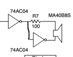
the ultrasonic transmitter uses 40 Khz frequency pulses with pk-pk voltage nearly 18 volts. the circuit i have uses nand gate, transistor and then not gate amplify the pulses coming from 555 timer. what can i use instead of parallel not gate to amplify the pulses of 40 khz and 9V to 18V?
 

Umm, you can't use logic gates to amplify a signal. Are you saying you're trying to step up logic levels to 18 V? If your signal is simply logic levels, you can use a transistor or MOSFET to step the signal up to your required voltage.
 

if you know the impedance of the crystal, you can step up the voltage with a miniature autotransformer coil and get several hundred volts easily.

or

consider a mini automotive ignition coil,

That should give you at least 1K gain
 

Umm, you can't use logic gates to amplify a signal. Are you saying you're trying to step up logic levels to 18 V? If your signal is simply logic levels, you can use a transistor or MOSFET to step the signal up to your required voltage.
Logic inverters (why are they called NOT gates when they do not gate anything?) are frequently used as amplifiers and are frequently paralleled to increase their output current. They can have an 18V supply so their output can be as high as 18V p-p.
 

is there any alternative of logic inverters?
 

they have Mhz piezo drivers that run off hundreds of volts in pulses too for imaging.
But if you use two inverter buffers and drive differentially that will double your output.


Again a simple small coil winding around ferrite core with a tap for primary will boost signal significantly. They use this to make piezo alarms with 100Vac from 9v.that are 110dB.
.
 
Last edited:

i have tried using lm741 but it didnt work.
plz specify which opamp to use and if possible provide me the circuit.
thanx....:)
 

LM741 does not have enough slew rate

you can run CMOS off a wide range of voltages and get lots of bandwidth and also use the 6 amps in different ways... One way. to double the voltage
Screen shot 2012-05-06 at 1.08.13 PM.PNG
but keep in mind this piezo has the same equiv circuit as a quartz crystal in the MHz.
Screen shot 2012-05-06 at 1.03.18 PM.PNG

So with a simple self-bias 10MΩ resistor, the piezo will oscillate when put across an invertor with the recommended load capacitance. (pF)
 

i dont have IC 74AC04 for inverter so what can i use instead?
plz help.
 

Any other avaliable inverter IC, prefereably paralelling as much as possible.

+++
 

The 741 opamp doesn't work because it is 45 years old and was designed for DC and low frequencies.
ANY modern audio opamp can amplify 40kHz.
 

Status
Not open for further replies.

Similar threads

Part and Inventory Search

Welcome to EDABoard.com

Sponsor

Back
Top