Continue to Site

Welcome to EDAboard.com

Welcome to our site! EDAboard.com is an international Electronics Discussion Forum focused on EDA software, circuits, schematics, books, theory, papers, asic, pld, 8051, DSP, Network, RF, Analog Design, PCB, Service Manuals... and a whole lot more! To participate you need to register. Registration is free. Click here to register now.

Object intersect in HFSS

Status
Not open for further replies.

baby_1

Advanced Member level 1
Joined
Dec 3, 2010
Messages
415
Helped
1
Reputation
2
Reaction score
1
Trophy points
1,298
Activity points
4,277
Hello
Object intersect driving me crazy.I did different part of Ansoft tutorial and I got "Object .... intersect ....". I use HFSS design kit to get a fine designed project but as I want to analyze it shows me again "Object .... intersect ...." and it stops run.
what is my mistake? or I didn't set a setting

- - - Updated - - -

Hello
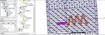
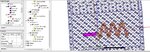
Here is a full ready project with "HFSS design kit" and it shows me again
9.JPG
and Here project file
View attachment Project5.rar
 

The coaxial you modeled cuts the air box. Again this is not allowed in HFSS. you should Boolean subtract the coaxial from the air box and assign the wave port at the facce of coaxial pin.
Regards
 
  • Like
Reactions: baby_1

    baby_1

    Points: 2
    Helpful Answer Positive Rating
Yes your right.
and Could you tell me how can excite a coaxial cable?
because I see for a project someone sets Terminal for solution type and set wave port for coaxial input and set terminal for it again.
why does he set both of excitation for input?
 

sorry but i didn't understand could you clarify your question?
 

Excuse me
I want to know how can excite a coax cable In "Teminal" mode of "solution type"?
10.JPG
 

the wave port should be a surface on the terminal of the coaxial. It should also be in the radiation boundary.
 
  • Like
Reactions: baby_1

    baby_1

    Points: 2
    Helpful Answer Positive Rating
I dont have HFSS on this PC. Sorry.
 

Sorry again I want to take your time
I get an idea from output of "HFSS design kit". As you see in this picture , wave-port excitation is defined in the radiation box and it seems with a PEC "Port-gap" terminate it's radiation in back.
20.JPG
but as I did the same procedure I don't get any result
21.JPG

22.JPG
 

Attachments

  • 20.JPG
    20.JPG
    192.8 KB · Views: 109
  • 20.JPG
    20.JPG
    193.8 KB · Views: 122

This pec port-gap is used if you intend to place the wave port inside the radiation box. You should take care that the length and width of the wave port should be 10 times more than the radius of the coaxial conductor.
 

Thank you for your response

You should take care that the length and width of the wave port should be 10 times more than the radius of the coaxial conductor.

As I check "HFSS design kit" the wave_port plane(circle) radius is (3.8765mm) and the inner coaxial conductor radius is (1.156mm) but it works fine but my design with the same size doesn't work!! or I didn't catch your explnation
 

the dimensions of the wave port would not make an error. But it would not be enough for the the mode to propagate properly which may lead to non accurate results. If you made the wave port on the coaxial conductor face and place a pec thickened sheet before it that would be enough for your design to work.
 

Sorry . It seems the port excite very well but nothing inject to antenna feed pin.
20.JPG
21.JPG
however as you see I didn't unit them because to prevent "object intersect" error but the are in the same(2D) plane
22.JPG

what is my mistake?
 

If both are pec then you can unite them and i prefer you to do so in order to know what is wrong.
 

Thank you a lot for your guidance
both of them are PEC but I can't unit them because as I understand two 3d material in different situation ( for example two different media) can't join and we should do something that they only touch each other not or be tangent.(I checked and it shows me "intersec" error ) (Am I right?)
could you give me a few pages of a good reference to find my problem or what is really we are forbidden to do or not in HFSS?
 

I have no reference right now. but i am sure that two solids of the same material can be combined, please check that they are of the same material and try to unite them. If this error appears please attach it.
 

Thank you
here is my design before unit operation
30.JPG
after unit operation
31.JPG
So I get the intersect error (Teflon of coax and inner conductor)
32.JPG

but I'm wondering why does the output of "HFSS design kit" without unit the two feed line work without any problem?but my doesn't
It is related to only they didn't attach to each other or I did something wrong.
 

what is coax out and coax in. The teflon could not be united with pec. pec should be subtracted from teflon.
 

Thank you so much, it works
but unfortunately I don't have any pattern and E-filed around the antenna.it is because of I don't have outer conductor of coaxial cable or I did something wrong?but I think it doesn't related to outer conductor because many simulations that see in internet the coax doesn't have any outer conductor
20.JPG
 

No one can guide me how to fix this problem?
 

Status
Not open for further replies.

Part and Inventory Search

Welcome to EDABoard.com

Sponsor

Back
Top