Continue to Site

Welcome to EDAboard.com

Welcome to our site! EDAboard.com is an international Electronics Discussion Forum focused on EDA software, circuits, schematics, books, theory, papers, asic, pld, 8051, DSP, Network, RF, Analog Design, PCB, Service Manuals... and a whole lot more! To participate you need to register. Registration is free. Click here to register now.

Numerical Integration in C

Status
Not open for further replies.

north2012

Member level 3
Joined
Apr 1, 2013
Messages
63
Helped
1
Reputation
2
Reaction score
1
Trophy points
1,288
Activity points
1,813
Hi,

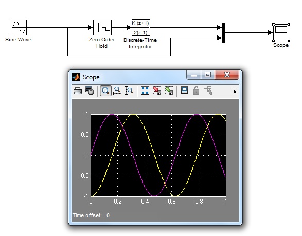
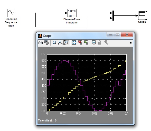
I would like to implement integration of input signal to my AVR based system. Input signal will be sampled with ADC and output will be sent to DAC. For example, if input signal is x(t)=Xsinwt => ADC => x[k] => integration => y[k => DAC => y(t)=-Ycoswt

Ideas?
 

I worked with f=10 Hz so I chose T=0.003 sec and with 30 samples I have signal sampled very nice. When I tried with discrete-time integration (x-input, y-output)

y[n]=y[n-1]+0.5*T*(x[n]+x[n+1]), n>0, T=0.003

I changed a lot of y[0]=IC, but with no success. Do you know what can be the problem and how to determine IC automatically, because input signal can be in wide range of different types.

- - - Updated - - -

Please find attached file with samples and graphs for y(0)=100.

View attachment Rezultati semplovanja i integracije.pdf
 

It's mysterious how you arrived at the y[n] numbers shown in the table. Apparently you are performing some kind of hidden truncation during the calculation. Not even x[n] sign seems to be processed correctly.

I believe that y[n]=y[n-1]+T*x[n] (staircase instead of trapezoidal integration) will be sufficient in most cases.
 

Yes, you can use the staircase approximation, as suggested by FvM to simplify the calculation.

However I think you have problems in the calculation of the formula (that is correctly written), probably there is an implementation error. Could you post your code ?

IC just shift up and down the curve, but the shape remains the same. Changing the sampling time T you change the scale factor (amplitude) of the resulting waveform.
Put your samples in an excel file and apply the formula: you should see the correct result
 

Hello,

Thank you very much for your answers.

1. My code (written in C, mikroC PRO for AVR compiler)
Code:
#define ADC_ENABLE ADCSRA |= (1<<ADEN)
#define ADC_DISABLE ADCSRA &= 0x7F
#define ADC_START_CONVERSION ADCSRA |= (1<<ADSC)

void adc_mega32_init(void)
{
  ADCSRA = 0x00; //switch off adc
  ADMUX = 0xC0; // adc input 0, ref = 2.56 V...
  ADCSRA = 0x86; //start
}

int adc_mega32_read(void)
{
  char i;
  int ADC_temp, ADCH_temp;
  int ADC_var = 0;

  ADC_ENABLE;
  ADC_START_CONVERSION; // dummy
  while(!(ADCSRA & 0x10));
  ADCSRA|=(1<<ADIF);

  for(i=0;i<8;i++) // 8 samples
  {
  ADC_START_CONVERSION;
  while(!(ADCSRA & 0x10)); // done???
  ADCSRA|=(1<<ADIF);

  ADC_temp = ADCL; //  ADCL register
  ADCH_temp = ADCH; //ADCH
  ADC_temp +=(ADCH_temp << 8);
  ADC_var += ADC_temp;
  }

  ADC_var = ADC_var >> 3;
  ADC_DISABLE;
  return ADC_var;
}

void main ()
{
    char buffer[15];
    int m;
    unsigned int x[30], y[30];
    
    float T = 0.003;
    adc_mega32_init();
    UART1_Init(9600);
    delay_ms(100);
    
      for(m=0; m<30; m++)
      {
        x[m] = adc_mega32_read();
        delay_ms(3);
      }
      
      for(m=0; m<30; m++)
      {
        inttostr(x[m], buffer);
        Uart1_write_text(buffer);
        Uart1_write(13);
      }
    Uart1_write(13);
    
    y[0]=200; //Initial condition
    
    for(m=1; m<30; m++)
    {
     y[m] = y[m-1]+T*x[m];
    }
    
    for(m = 0; m <30; m++)
    {
      inttostr(y[m], buffer);
      Uart1_write_text(buffer);
      Uart1_write(13);
    }
    
    while(1)
    {}
}

2. I tried to perform calculation on samples in Excel (as you suggested) but the results are still wrong...
 

In the integration operation, T*x[n] is truncated to integer. Less than 2 of 10 ADC bits are kept. Please reconsider.
Code:
y[m] = y[m-1]+T*x[m];

Maybe your Excel code involves truncation, too. Otherwise you would see a pretty cosine graph.
 

I tried with

float y[30];
....
y[m] = (float)(1.0*y[m-1]+1.0*x[m]*T);

but result is the same. Even if I perform calculations on the paper, for example
x[n]={404, 448, 489, 526, 557, 580, 595, 600, 594, 579, 555, ...}

y(0)=200 // IC

y(1)=200+0.003*404 = 201.212
Y(2)= 201.212 + 0.003*448 = 202.556
Y(3)=202.556+0.003*489 = 204.023
...

and obtained curve is some kind of line...

When I did the same (with the same frequnecy, sampling time, etc.) in Matlab Simulnk, I got very nice results.

9944213200_1406707223.jpg


- - - Updated - - -

Very odd... When I used obtained samples as source to discrete-time integrator block in MATLAB I got the same results as with my microcontroller and Excel.

4075320300_1406707923.jpg
 

I found very useful application note **broken link removed** where are very well explained algorithm and source code for velocity calculation from acceleration.

They used very simple and easy to understand formula for integration
velocity[1] = velocity[0] + acceleration[0] + ((acceleration[1] - acceleration[0])>>1)

But, when I tried to implement this formula on a(t)=1*sin(2*pi*50*t), so RMS is 0.707, I got for v(t) cosine line but RMS is 11.63. Expected value is 0.22 V.

https://obrazki.elektroda.pl/1864101900_1407486657.jpg

Does anyone know how to perform proper scaling?

Thnaks.
 

In the article the two methods trapezoidal (the original you wanted to use) and the simplified staircaise are reported. So there is nothing new with respect to that already said.
I tried to insert into an excel file these two methods and the results obtained are correct. I used sin(w*t) so the integral will be cos(w*t)/w.
In your case probably you forgot to multiply by ΔT (sampling time), I think you used just the normalized values where ΔT=1
 

Status
Not open for further replies.

Part and Inventory Search

Welcome to EDABoard.com

Sponsor

Back
Top