Continue to Site

Welcome to EDAboard.com

Welcome to our site! EDAboard.com is an international Electronics Discussion Forum focused on EDA software, circuits, schematics, books, theory, papers, asic, pld, 8051, DSP, Network, RF, Analog Design, PCB, Service Manuals... and a whole lot more! To participate you need to register. Registration is free. Click here to register now.

Not getting the FFT of COMPARATOR

Status
Not open for further replies.

sagar.dhange

Newbie level 4
Joined
Sep 12, 2012
Messages
6
Helped
0
Reputation
0
Reaction score
0
Trophy points
1,281
Location
VNIT Nagpur, India
Activity points
1,329
Hello everyone,
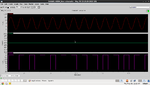
I designed the hysteresis type of comparator using internal positive feedback......for 0 to 1.8v supply....
I am getting the proper output.....
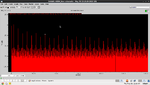
But when I am doing the FFT of that, the harmonic at the fundamental frequency(i.e. at input frequency) is coming out to be +1.18dB (positive) but it should be negative......
So will any one please help me how to achieve this....??

I am attaching the screen shot of my design.....please go through it..........

Waiting for your reply's.......
Screenshot-1.png
 

Can you show input and output waveforms so we can see what the problem is?
 

Hi......
I am attaching the input and output screen shot to it......
1) upperone is +ve input to comparator
middle one is -ve input to comparator i.e. reference at 900m
lower is output of the comparator...
2) 8192 point FFT of the output at 10KHz of input freq.
 

Attachments

  • Screenshot-2.png
    Screenshot-2.png
    40.5 KB · Views: 74
  • Screenshot-3.png
    Screenshot-3.png
    37.8 KB · Views: 84

The waveform and FFT both look correct. The fundamental should be about +1dB. Remember, the amplitude of the fundamental is greater than the amplitude of the square wave.
 

Thanx a lot........
One more problem........
I am using this comparator in Sigma Delta ADC for Audio range (upto 20KHz)..
But the higher harmonics(2nd, 3rd, ....) are not suppressing as required.....
Any suggestions for that..........
 

What do you mean? Comparators and ADCs aren't supposed to suppress harmonics. An ADC should have an anti-aliasing filter to remove anything in the input that is above the Nyquist frequency.
 

I designed a two stage class A/AB amplifier whose lower 3dB Band Width is coming out to be 21KHz......
Also I designed the above comparator..........
And with the help of these 2 blocks I designed Sigma Delta ADC with 1 bit DAC in feedback path.......
Amplifier is used as an integrator(using R and C).......
But at the output the FFT of this entire system is showing many harmonics and also I am unable to get the required Band Width in PSD vs Freq graph..........
Please help me to solve this problem.........
In this case also I have to use anti aliasing or what....???

- - - Updated - - -

Please go through the following link........I attached the required graphs there regarding the above problem of Sigma Delta ADC........


https://www.edaboard.com/threads/289963/#post1239716

- - - Updated - - -
 

Status
Not open for further replies.

Part and Inventory Search

Welcome to EDABoard.com

Sponsor

Back
Top