zoulzubazz
Member level 5

- Joined
- Apr 26, 2012
- Messages
- 87
- Helped
- 3
- Reputation
- 6
- Reaction score
- 3
- Trophy points
- 1,288
- Activity points
- 2,040
hey guys,
trying to test the usability of the ADA4870 high speed high current opamp, datasheet here:
https://www.analog.com/media/en/technical-documentation/data-sheets/ADA4870.pdf
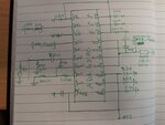
I have connected the ADA4870 in a configuration (as shown in picture attached with post) very similar to the evaluation board presented in figure 5 here
https://www.analog.com/media/en/tec...luation-documentation/EVAL-ADA4870_UG-685.pdf
the amp in connected as an non-inverting amplifier set for a gain of 5 (have tried gain of 10 too) but the setup is unable to provide a gain greater than one. The supply is +-17V and the input is 2Vp-p. A clean sinusoid is reproduced but not at the level of gain required. Could someone please shed some light on what could be wrong. Thanks very much.

