Continue to Site

Welcome to EDAboard.com

Welcome to our site! EDAboard.com is an international Electronics Discussion Forum focused on EDA software, circuits, schematics, books, theory, papers, asic, pld, 8051, DSP, Network, RF, Analog Design, PCB, Service Manuals... and a whole lot more! To participate you need to register. Registration is free. Click here to register now.

Nokia 3310 LCD shows only 5 rows of byte-wide pixels

Status
Not open for further replies.
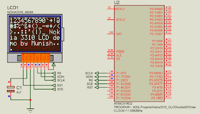
nokia 3310 lcd driver

All displays work the same way, if you follow the correct datasheet procedure.

Do not think that because you did some bypass and shortcut here and it works, it will work with all similar 3310 lcds, it may not.

For example, NEVER leave /SCE pin tied down (grounded), it should return to UP level after commands or data is sent.

The fact that grounding /SCE works for one unit, it doesn't mean it will work for other. Just control /SCE according to datasheet, if not you may experience strange results.

Remember that using PC Parallel port doesn't mean everything is perfect, it is not. Parallel port may receive unexpected commands from windows, mostly if using Windows XP/ 2000/ NT, Vista. Windows WILL interfere with your interface manipulation. I know very much about that. NEVER expects parallel port to be as clean as you think it should, it WILL NOT.

This fact may be more pronounced if you use a long parallel cable. For testing purposes, NEVER use a parallel cable longer than 2 feet, and above all, use a shielded cable. You have no idea how much electromagnetic noise is presented around a PC, mostly at its back close to the power supply.

Don't believe me? just approach a portable AM radio to the back of any PC and listen to the strong interference.

When testing prototypes as the Nokia LCD, use a clean microcontroller, as an AVR (Atmel) or even a PIC, powered by clean batteries (not 60Hz power supply), at least 2 meters from any PC or even fluorescent lamp reactor (mostly those electronic lamps). So you will not have any interference surprises.

Remember; NOKIA would NOT change the LCD controller at the end of that model's life... It still the Philips PCD8554, but the circuitry may be a little different, more noise sensible, etc. The interface circuit may be manufactured with different parts that may behave different under rare circunstances.

For example, many (MANY) years ago I produced car alarms using the uA555 as a timer. The circuit used a non documented function of the 555, when SET and RESET were active at the same time, it saved me money and parts on the circuit board. After few months I purchased another lot of 555, but the supplier sent me not uA555 but NE555. The datasheet was exactly the same, but the circuit board didn't work as expected. Both ships behave differently when SET and RESET are active simultaneously. One understand SET and enter that state, the other kept in RESET, messing my circuit board.

The story here is that using the chip out of the datasheet, may result in different consequences.

wagnerlip
 

nokia pcf8813 driver

I am also having the same problem as zinahe. My solution to the problem is by setting the cursor to start at Y=1(bank 1) and adding vertical offset.

I think the new nokia 3310 uses ST7548T or similar LCD driver by Sitronix.
 

philips pcd8544 parallel port pc

I live in India.

I have also got a similar problem, which was rectified by the display offset settings. However, the wrap-around feature used to drop two characters of 6x8 Font used with the display, which I corrected by using a software address counter. Hence I think the display controller must be 96*xx.

The LCDs require a large VOP value, i used command 0xD0 to get a display dark enough.

For backlighting the display, I use 2 SMT extremely small white LEDs used in mobile LCD modules (mine was from a broken 1600 LCD) on the left and the right side of the display.
 

Hello everyone,

I have built a program for driving the Nokia 3310 LCD. I bought 2 of these LCDs recently, while I had another older one with me(without the plastic frame). Now I am facing a problem interfacing these new LCDs that the display is garbled on both. The older one displays correctly (as in Proteus):
Clipboard02.png

What I am getting on both new LCDs is:
Clipboard03.jpg

The older LCD:
Clipboard01.jpg

see also the difference in graphics display for older & newer:

https://lh5.ggpht.com/_Njeu3g-Ugm0/SwEr1nA5jqI/AAAAAAAABHM/7qrn4xQa7MI/s800/Clipboard04.jpg
https://lh6.ggpht.com/_Njeu3g-Ugm0/SwEr2p9aY4I/AAAAAAAABHQ/garYdv61FrU/s800/Clipboard05.jpg

The newer LCDs are not displaying the top 3 rows of the image & the last 11 rows of the LCD are always filled with random(?) dots. I also think the LCD is writing some data off-screen as some characters are not visible at all. I am using 5V for all the LCDs (according to some websites) & here's the (standard) initialization:

lcdcmd(0x21); // Activate Chip and H=1.
lcdcmd(0x80 + 90); // contrast value (0 to 127): 60 enough for old LCD & 90 for new
lcdcmd(0x13); // Adjust voltage bias.
lcdcmd(0x20); // Horizontal addressing and H=0.
lcdcmd(0x09); // Activate all segments.
clrdisp(); // Erase all pixel on the DDRAM.
lcdcmd(0x08); // Blank the Display.
lcdcmd(0x0C); // Display Normal.
pixelXY(0,0); // Cursor Home.

The commands for setting contrast work (but different values for old & new, as you can see above)

So finally here are my queries:

1) I suspect it is some different controller than PCD8544. Is anyone aware of a different controller than this in Nokia 3310 LCD?

2) Is 5V safe for this LCD/controller? datasheet says 7 V is absolute max.

3) I saw some people talking about setting an offset. I added the reserved command lcdcmd(0x08+n) to shift display n rows up. But I need to shift it 3 rows down. What's the command for that?
 

mUNISH,

This is exactly as was in my Display before the new code,

Actually the display chip drives 102x67 pixels, but only the top left 84x48 pixels are displayed.

This explains why the 11 rows are garbage, as they have not been cleared yet!
They are filled with undefined/random data after a reset.
The display driver wraps a row (8 pix) after 102 pixels and not 84 pixels. That is why the display is 'eating up' 3 characters (6*3=18 pixels).

The Driver chip has no documented command to shift the display down by some pixels, but still there is a workaround.

Remove bank 0 form the display by shifting the display 5 rows up using 0x45 command. It will now comprise of Banks 1-6. Use Banks 1-6 for displaying. Use a software address counter by storing the current x and y address and changing the row manually.

I have been able to make 3 such 'defective' displays work 'normally' using this code snippet written using SDCC for 89S52:

Unfortunately, I broke the LCD just after experimentation and don't have a photograph for it. But I can vouch that it will work 200% for sure.

Use NEW=1 for 'defective' display, NEW=0 for older displays.

Code:
#define NEW 1 // For new lcd, set it to 1, for old 0

unsigned char cx,cy;

#define clockSCL() SCLK=0; SCLK=1;

// Software SPI to LCD
void lcdOut(unsigned char dat)
{
    CS=0;
    SDIN=dat&0x80;
    clockSCL();
    SDIN=dat&0x40;
    clockSCL();
    SDIN=dat&0x20;
    clockSCL();
    SDIN=dat&0x10;
    clockSCL();
    SDIN=dat&0x08;
    clockSCL();
    SDIN=dat&0x04;
    clockSCL();
    SDIN=dat&0x02;
    clockSCL();
    SDIN=dat&0x01;
    clockSCL();
    CS=1;
}

// Write a command to LCD
void lcdCom(unsigned char dat) { DC=0; lcdOut(dat); }

// Write data to LCD
void lcdData(unsigned char dat)
{
    DC=1; lcdOut(dat);
#if NEW
    // Implementation of a software address counter
    cx++;
    if (cx > 83)
        lcd_gotoxy(0,cy+1);
    if (cy > 5)
        lcd_gotoxy(cx,0);
#endif
}

// Initialize the LCD
void initLCD(void)
{
    CS=1;
    RST=1;
    _delay_ms(200); // Software delay routine - change with your own
    RST=0;          // Hardware Reset Initiation
    _delay_ms(200); // Software delay routine - change with your own
    RST=1;

    lcdCom(0x21);   // Extended Instruction Set
#if NEW
    lcdCom(0xE4);   // A large VOP for new displays
    lcdCom(0x45);   // New LCD Correction (Y offset +5)
#else
    lcdCom(0x90);   // VOP values for older displays
#endif
    lcdCom(0x06);   // Temp. coefficient
    lcdCom(0x13);   // VBias
    lcdCom(0x20);   // Normal Instruction Set
    lcdCom(0x09);   // All on (display black)
    _delay_ms(750); // Software delay routine - change with your own
    clearLCD();     // Clear DDRAM
    lcdCom(0x08);   // Display Blank
    _delay_ms(50);  // Software delay routine - change with your own
    lcdCom(0x0C);   // Normal Mode
    home();         //Home cursor
}

// Cursor positioning
void lcd_gotoxy(unsigned char x, unsigned char y)
{
    lcdCom(0x80|(x&0x7F));  // X Address Set 1XXX XXXX
#if NEW
    // Use bank 1-6 for new displays
    lcdCom(0x40|((y+1)&0x07));  // Y Address Set 0100 0YYY+1
    cx=x;cy=y;
#else
    // Use bank 0-5 for old displays
    lcdCom(0x40|(y&0x07));  // Y Address Set 0100 0YYY
#endif
}

// Clear DDRAM
void clearLCD()
{
    int i;
    home();
    for (i=0;i<504;i++)
        lcdData(0x00);
}

//cursor home
void home() { lcd_gotoxy(0,0); }
SCE, SDIN, RST and SCLK have their usual meanings.
And yes, regarding your other queries:

The controller is definitely different from the earlier PCD8544, but is compatible with its opcodes, and will certainly work 100% with the modifications proposed.

The Nokia 3310 displays will work fine from 3V to 5V VCC. The 7V Mentioned in the datasheet is about the LCD Driving voltage, which is internally generated from the supply voltage through a charge pump inside the IC, as a high potential is required to change the phase of liquid crystals inside the LCD.

For any code compilation errors or further display problems, do PM me with a proper screenshot of the LCD so that I may help you further.

With regards
Abhishek.
 

Hi Abhishek,

First of all thanks to your kind & detailed reply.

I had done some testing on this LCD by putting many characters & carefully observing exactly where the next (visible) char came. I observed that the controller inside the LCD is 102*80. Seems China people have brought too many "flavours" of the PCD8544. Like yous is 108*67. And the worse part: they are grossly undocumented on the internet.

I had done exactly what you said: discarding first 5 pixel rows & taking row 2 to be the first. I had posted this problem on 8052.com also but I forgot to put back the solution here :|. Anyways here's the link: **broken link removed** I have posted the complete details there.

Once again, thanks for your help. I greatly appreciate it! :D
 

Status
Not open for further replies.

Similar threads

Part and Inventory Search

Welcome to EDABoard.com

Sponsor

Back
Top