Continue to Site

Welcome to EDAboard.com

Welcome to our site! EDAboard.com is an international Electronics Discussion Forum focused on EDA software, circuits, schematics, books, theory, papers, asic, pld, 8051, DSP, Network, RF, Analog Design, PCB, Service Manuals... and a whole lot more! To participate you need to register. Registration is free. Click here to register now.

Noise problems in electret mic preamp

Status
Not open for further replies.

erics1007

Newbie level 3
Joined
Dec 4, 2011
Messages
3
Helped
0
Reputation
0
Reaction score
0
Trophy points
1,281
Activity points
1,334
Hello,

First time I've posted, enjoy the forum and the great information.
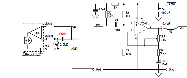
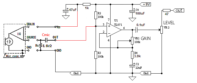
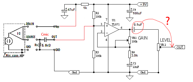
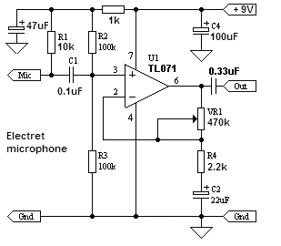
I'm building a small preamp for my telephone headset so I can record conference calls on my computer. I've used several op amp circuits for electret mics, most recently one posted by Audioguru in response to another post (below). I'm getting the same result with all these circuits - a constant white noise that increases with the gain of the amp. I would describe it as "snow" - although I'm not sure what the technical term for it is.

I've assembled the circuit on a breadboard and read about some of the grounding issues in other posts and am wondering if that's my problem. I actually assembled this on a proto-board and had the same noise problem. This is a drilled board with isolated copper contact points around each hole - not a PCB with power and ground planes.
Any help would be greatly appreciated. Thanks very much.

87_1323149928.png
 

WELCOME to EDAboard


Practically speaking you can record the head phone signal directly by isolation transformer and no further gain is needed as you are likely to connect to Line in point o9f your PC. All the best
 
Last edited:

Thanks for the reply mvs sarma
I'm not sure why the first part of your reply didn't show up - I'll paste it here:

I presume that you are connecting the circuit to the telephone line point with some sort of capacitive coupling. Instead i suggest that you may use an isolation transformer and connect at the pins where the earpiece of telephone is connected( yes, you have to access from inside). perhaps R1 is not needed.

th e circut would have high gain as it is designed for cap mic. for head phone signal amplification , you don't need that much gaim,

Practically speaking you can record the head phone signal directly by isloation transformer and no further gain is needed as you are likeley to connect to Line in point o9f your PC. All the best


This noise isn't coming from the telephone connection - I'm using a cordless phone and connecting a headset to the 2.5mm earphone jack.
Also, I'm getting this noise when I simply plug the mic output from my headset directly into the amp and put the output into my computer's audio board.
 

Later i had edited to make it simpler for you.
making an amplifier is encouraging , but when we can manage recoding without it, why to use it.

the specific amplifier is meat for high amplification of a signal coming out of a capacitor mic.
the signal both incoming and out going are clearly amplified and wont need further . if you are connecting to the headset jack of the cordless, i suggest to identify the common and the pin( tip or sleeve) going to headphones( not the microphone). connect it to an isolation transformer like the ones used in former radio receiver audio amplifiers. Use the secondary to connect to your PC's line in jack.
it simply works. all the best
 

i dont know whether you are referring the noise pickup to hum pickup.
if it is so , use shielded wires in 'in' out' of your tlo71 circuits adequately.
 

he is referring to what he said., SNOW. It is a sort of high frequency HASHing noise.
 

My preamp circuit for an electret mic has very high gain when the trimpot is turned up. The TL071 is an inexpensive audio opamp so its noise level is not very low. Therefore the high gain amplifies the noise from the opamp. Simply turn down the trimpot to reduce the gain or use a better opamp. An OPA134 opamp has much less noise.
Some cheap electret mics are also noisy.

EDIT: i forgot to mention that the TL071 and some other wide bandwidth opamps oscillate at a high frequency which causes noise when they drive the capacitance of a shielded cable. Connect a 100 ohm resistor between the output of the opamp and the cable to fix it.
 
  • Like
Reactions: Aenima

    Aenima

    Points: 2
    Helpful Answer Positive Rating
Thanks Audioguru - I'll put that resistor in. Also had a little 'pilot error' here with an open lead causing some of my issues, I think.
Been gone for a couple weeks. Let me get back to this and I'll post an update.
Again, thanks to everyone for the input.
 

Hi, everybody. I am first time at your remarkable forum.

I build a binaural microphone for my camera.
As the amplifier, I chose the circuit from the first message.
I've read a thread, and by Audioguru's advice decided to make it with OPA2132 and Primo EM173 microphones.
As a result I have this circuit for inclusion of a microphone and the amplifier.

The left picture is taken from datasheet on Primo EM 173.
And I've got some questions.
First question:
Are both Rs and Cmic on a microphone necessary?
What values should these elements have to plug the microphone to this amplifier circuit.
I've made a prototype, and it works. But I am not sure that I did everything correctly.
Second question:
At connection of the device to a camera entrance, the sound are written, and everything works. But, when I set the volume level of VR1 to a minimum, the sound all still goes and is rather loud. When to a maximum it becomes much more loudly. How to make that it would be possible to regulate volume from silence and to normal level?
And the third question:
What wires are better to use for microphones?
The maximum wire length from the amplifier to a microphone is 1 meter.
It is better to use twin-core cable with the shield?
Or better single-core with the shield?

In addition many thanks for answers, I look forward for your help.
 

Attachments

  • Pic.jpg
    Pic.jpg
    51 KB · Views: 339

What you constructed may work as you say, although this is the typical way to hook up an electret mic. The green parts show where I removed components, and drew a patch wire.


The electret puts out a stronger signal (especially with a 9V supply) than the common dynamic mic. Therefore you can reduce the gain.

As for cable, shielded single-conductor mic cable is sufficient. We ran a couple dozen feet of it from our electret mics to the PA amplifier. Hum was not a problem because the preamp was installed in the mic housing. Hence the signal that came over the wires was low impedance.
 

Most electret mics have only 2-wires. They have good sensitivity but loud sounds overload them.
Your mic has 3-wires. Then its Jfet has no voltage gain (low sensitivity) but loud sounds do not overload it.

I removed the 10k resistor that powers a 2-wires electret mic. Now your mic has plenty of power supply voltage to work well.

EDIT:
RV1 is not a volume control, it is a gain control. The gain can be very low (but will not mute sounds) to very high.
 

Attachments

  • Electret mic (3-wires) preamp.png
    Electret mic (3-wires) preamp.png
    25.6 KB · Views: 415

I appreciate your help very much! Many thanks for your answers!
Now I see the difference between the volume and gain.
So, I have to use twin-core cable with a shield.
Can I use a 0.1uf capacitor as Cmic, in this case?
And could you please recommend me an easy way to create a volume regulator for this circuit?
 

The formula for a coupling capacitor is 1 divided by (2 x pi x f x R), where f is the cutoff frequency. The level of the cutoff frequency is reduced -3dB (0.707 times) from the level of higher frequencies and lower frequencies are reduced -6dB (half) for each lower octave.

Cin feeds the two 100k biasing resistors so R= 50k ohms. Then with 0.1uF the cutoff frequency is 32Hz which is fine for voices but the capacitor should be 0.22uF or 0.33uF for music.
 
Last edited:
  • Like
Reactions: Aenima

    Aenima

    Points: 2
    Helpful Answer Positive Rating
Many thanks for your answers once again!
It is very valuable information for me.
I have the last question!
Tell, the scheme of volume control can be made like this? :
 

Tell, the scheme of volume control can be made like this?

It looks as though VR2 is the volume control. Chances are that it works best there, after applying some gain (rather than to attenuate the mic signal early).

If you wish you can try putting the volume control in other places.
 

The volume control VR2 is connected backwards. Then it SHORTS the output when it is turned down which cuts low frequencies more than high frequencies and causes severe distortion.
It should be connected as a voltage divider.
 
  • Like
Reactions: Aenima

    Aenima

    Points: 2
    Helpful Answer Positive Rating
Many thanks to everybode here for your help and the special thanks to Audioguru!
It was absolutely great to get help from you, guys! I've learned a lot here.
Now I'm going to finish my device as fast as possible.
And then I'll share my PCB and audio test results.
 

Could you tell me please, whether it is necessary to transfer the capacitor after the resistor, or to leave without changes?
Is it also necessary to put something on the output after the resistor?


The output capacitor blocks the DC at the output of the opamp from damaging the volume control. It also prevents the opamp from driving a DC load.
The output of the volume control has a DC voltage of 0V which is fine for feeding the input of most amplifiers.

You should calculate the -3dB frequency of the 0.1uF output capacitor and the resistance of the volume control.
If the volume control is 10k ohms then with a 0.1uF coupling capacitor the cutoff frequency is 160Hz so low frequencies will be reduced.
If the volume control is 100k then the cutoff frequency is 16Hz and low frequencies are fine.
If you want a 10k volume control and want low frequencies then change the capacitor to 1uF.
 
  • Like
Reactions: Aenima

    Aenima

    Points: 2
    Helpful Answer Positive Rating
Status
Not open for further replies.

Similar threads

Part and Inventory Search

Welcome to EDABoard.com

Sponsor

Back
Top