siva88
Newbie level 4

- Joined
- Jul 12, 2013
- Messages
- 6
- Helped
- 1
- Reputation
- 2
- Reaction score
- 1
- Trophy points
- 3
- Location
- chennai,india
- Activity points
- 51
Hi everyone,
I am working on a project where I control PMDC motor by switching on/off through mosfet (PWM control) by DSP controller, also I measure real-time current of the motor using LEM (LTS-15-NP) current transducer.
Well, the problem is I get noise in the current sensor output line when the PWM(or switched voltage) is given to the motor!!:sad:.
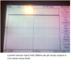
While the motor is turned-on the input voltage to the current sensor picks-up noise(see the below scope image).:???:
The output voltage of the current sensor has also have the same level of noise.

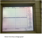
I also had a doubt that there could be some switching noise (some kind of transient peak current in the motor line while switching)!!. So I have measured the line current (while running) by putting a SERIES RESISTOR and measured with a scope, and it doesn't look like it has noise in the line.:|(below is the scope image for line drop voltage).

The ultimate problem is when I read this values through ADC, and plot the current graph all I get is some jumpy values so I do some software low pass filter, but still I have some noise, due to which I can’t able to interpret actual rise in current.
Instead of getting a “almost steady current “ I get some “jumpy steady current” which gives me lot of issues!!!:-x
Series resistor and some calculation:
Resitor = 0.5E
Voltage = 0.366v
Current(I) = 0.732A
Additional details FYI:
Motor = 180vdc PMDC motor.
Switching freq = 10Khz
Control: PWM control.
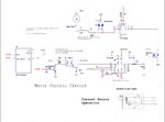
Added the circuit, It's not in full detail but I hope this will be of some help!!

If you can suggest or give an opinion on this, it will be of great help.
Thanks in advance.
I am working on a project where I control PMDC motor by switching on/off through mosfet (PWM control) by DSP controller, also I measure real-time current of the motor using LEM (LTS-15-NP) current transducer.
Well, the problem is I get noise in the current sensor output line when the PWM(or switched voltage) is given to the motor!!:sad:.
While the motor is turned-on the input voltage to the current sensor picks-up noise(see the below scope image).:???:
The output voltage of the current sensor has also have the same level of noise.

I also had a doubt that there could be some switching noise (some kind of transient peak current in the motor line while switching)!!. So I have measured the line current (while running) by putting a SERIES RESISTOR and measured with a scope, and it doesn't look like it has noise in the line.:|(below is the scope image for line drop voltage).

The ultimate problem is when I read this values through ADC, and plot the current graph all I get is some jumpy values so I do some software low pass filter, but still I have some noise, due to which I can’t able to interpret actual rise in current.
Instead of getting a “almost steady current “ I get some “jumpy steady current” which gives me lot of issues!!!:-x
Series resistor and some calculation:
Resitor = 0.5E
Voltage = 0.366v
Current(I) = 0.732A
Additional details FYI:
Motor = 180vdc PMDC motor.
Switching freq = 10Khz
Control: PWM control.
Added the circuit, It's not in full detail but I hope this will be of some help!!

If you can suggest or give an opinion on this, it will be of great help.
Thanks in advance.
