Continue to Site

Welcome to EDAboard.com

Welcome to our site! EDAboard.com is an international Electronics Discussion Forum focused on EDA software, circuits, schematics, books, theory, papers, asic, pld, 8051, DSP, Network, RF, Analog Design, PCB, Service Manuals... and a whole lot more! To participate you need to register. Registration is free. Click here to register now.

Noise & Electronic Ballast - 100Hz vs 400Hz

Status
Not open for further replies.

powersys

Advanced Member level 1
Joined
Nov 29, 2005
Messages
439
Helped
3
Reputation
6
Reaction score
2
Trophy points
1,298
Activity points
4,981
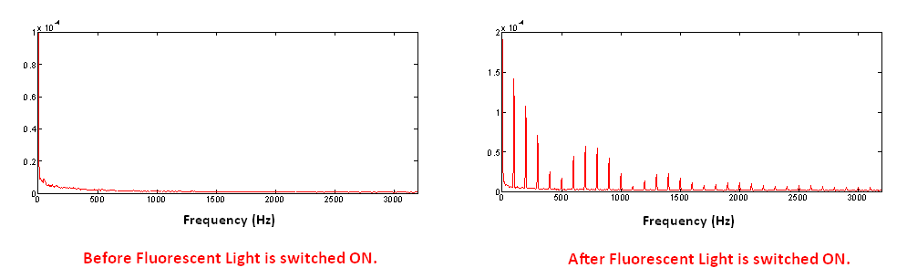
Recently I found out some noise, at about 100Hz, on the scope when I placed the probe of Channel-1 to one end of a coil and the GND-probe to another end of the coil. Before that I did not have such noise problem, which has been haunting me since few weeks ago. When I did FFT of the measured scope data, I found out several spikes at multiple frequencies of 100Hz (e.g. 100Hz, 200Hz, 300Hz, 400Hz...).

Yesterday, I found out that the noise was 'caused' by fluorescent lamp equipped with electronic ballast. When I switched off the lamp, the noise disappeared, and the spikes in FFT spectrum disappeared as well. I could hear some audible noise produced by the fluorescent lamp. According to the technician, the lamp is equipped with 400Hz electronic ballast.

[1] Is it 'conducted' or 'radiated' EMI?
[2] Why are the frequencies at multiple of 100Hz? Since the electronic ballast operates at 400Hz, in my opinion, it should be at multiple of 400Hz, (e.g. 400Hz, 800Hz, 1200Hz...). Pls correct me if I'm wrong.

Thank you very much
 

400Hz electronic ballasts don't exist, as far as I know. The technician is wrong, I think. You may want to check the 30 - 50 kHz range for conducted emmisions of the lamp. Or simply place an oscilloscope probe tip near the lamp, to check for an high frequency electric field.

Multiple of 100 Hz are trivial harmonics, generated by most electronic power supplies without power factor correction.
 

    powersys

    Points: 2
    Helpful Answer Positive Rating
Thanks. I confirmed again with the technician and he insisted that it's a 400Hz electronic ballast. May be he has wrong information from supplier. As the fluorescent light fitting is installed on the ceiling (which is about 5 meters above ground), I'm not able to place an oscilloscope probe tip near the lamp.

Added after 16 minutes:

Attached are the FFT of data captured by the scope. Pls refer to the FFT spectrum AFTER fluorescent lamp is switched on. It looks to me that the frequency peaks form an 'envelope' with several 'lobes' within the frequency range.


hello

you are seeing "aliasing" that is you are getting alias's of what's really there
 

Even if the lamp is operated at 400 Hz, the spectrum doesn't show it. The strange thing is however, that no 50 Hz fundamental is shown.
 

If the power supply is using a full wave rectifier, only odd harmonics of 50 Hz should be seen.
May it be the case, that the frequency axis has been shifted, so 0 actually means 50 Hz?

If so, an additional modulation at 400 Hz can possibly explain the higher frequency components. But it would be regarded as mains frequency harmonics by EMI regulations anyway.
 

Status
Not open for further replies.

Similar threads

Part and Inventory Search

Welcome to EDABoard.com

Sponsor

Back
Top