Continue to Site

Welcome to EDAboard.com

Welcome to our site! EDAboard.com is an international Electronics Discussion Forum focused on EDA software, circuits, schematics, books, theory, papers, asic, pld, 8051, DSP, Network, RF, Analog Design, PCB, Service Manuals... and a whole lot more! To participate you need to register. Registration is free. Click here to register now.

No base resistor for NPN driven by opto output?

Status
Not open for further replies.

cupoftea

Advanced Member level 5
Joined
Jun 13, 2021
Messages
2,035
Helped
45
Reputation
90
Reaction score
90
Trophy points
48
Activity points
10,413
Hi,
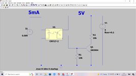
Please could i just do a reality check and confirm that no base resistor is needed in the attached NPN base drive?
LTspice and jpeg schem attached.

The NPN is just for a digital high/low output (from its collector) when the opto_diode current source is turned on (5mA) and off (0mA)
 

Attachments

  • opto.jpg
    opto.jpg
    166.6 KB · Views: 78
  • opto.zip
    581 bytes · Views: 59

danadakk

Advanced Member level 5
Joined
Mar 26, 2018
Messages
2,372
Helped
358
Reputation
734
Reaction score
538
Trophy points
113
Activity points
10,373
The design is depending on the CTR and input current. If limited on coupler input
current and the CTR limitations will limit current into external transistor
base. That being said I would think about using a R to limit input current
to external transistor should the coupler input driver fail with high current.
Keep in mind graphs are typical values, not worst case, in general in datasheet.


1652525395221.png


Regards, Dana.
 

KlausST

Super Moderator
Staff member
Advanced Member level 7
Joined
Apr 17, 2014
Messages
23,495
Helped
4,757
Reputation
9,535
Reaction score
5,172
Trophy points
1,393
Activity points
155,828
Hi,

What´s the benefit of the circuit?
To drive a BJT with some miliamperes base current while the bjt just drives below 1mA...

The bjt "overdrive" will lead to quite unsymmetrical timing behaviour.

Klaus
 

FvM

Super Moderator
Staff member
Advanced Member level 7
Joined
Jan 22, 2008
Messages
51,212
Helped
14,651
Reputation
29,580
Reaction score
13,795
Trophy points
1,393
Location
Bochum, Germany
Activity points
292,729
Asymmetrical timing is primarily caused by the optocoupler itself, but no timing requirements have been mentioned at all. You can however omit Q1, it has no purpose with 10k load.
 
Status
Not open for further replies.

Part and Inventory Search

Welcome to EDABoard.com

Sponsor

Top