Continue to Site

Welcome to EDAboard.com

Welcome to our site! EDAboard.com is an international Electronics Discussion Forum focused on EDA software, circuits, schematics, books, theory, papers, asic, pld, 8051, DSP, Network, RF, Analog Design, PCB, Service Manuals... and a whole lot more! To participate you need to register. Registration is free. Click here to register now.

nMOS Cap CV curve in SPICE

Status
Not open for further replies.

bio_man

Full Member level 2
Joined
Mar 30, 2010
Messages
144
Helped
2
Reputation
4
Reaction score
4
Trophy points
1,298
Activity points
2,698
Hello

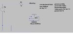
I'm simulating nMOS Cap to get estimate of the capacitance value. I used the old technique ( @ 1time constant, Vc=63.2%of Vin) then I found the capacitance ( C=time/R)

the circuit is attached, I used LTspice.

I want to get the CV curve for this nMOS cap as it is more practical, so can any one help me how to get this curve in the simulation?

second point, what is the difference between nMOS cap and pMOS cap because when I simulate the pMOS cap, I got no response?!

thirdly, is it better to use poly-poly cap instead of MOS cap? because it seems MOS Cap is non-linear ( it is changing based on the Vgs voltage)?
 

Attachments

  • nMOS_Cap.jpg
    nMOS_Cap.jpg
    79.5 KB · Views: 321

I can find the capacitance using C=Cox(WL), Cox=5.7fF/um2

but the issue I want to see the effects of different biasing and different frequency level,, and that is why I want to get the CV curve.

hope to get help from you guys,
 

I would try to emulate how semiconductor fab folks and
modeling folks test it - apply a voltage ramp, acquire the
current as you go, and do the math (integral of I being
Q, Q being C*V, at any given V your C is I/(dV/dt).
Pretty easy to set up if you have a Calculator in your
waveform viewer with a deriv() function. Or you could
dump raw data if it's ASCII SPICE (does anybody still
work that way?).

I=C*dV/dt would give you a nice simple result, in the I,
if you scaled your ramp dV/dt just-so. Like say 1V/1mS
then your C=I/1m. And your V is the (also scaled) time
axis.

NMOS vs PMOS - check polarity. You only see C-V swing
when you cross from accumulation to inversion. Outside
this you see roughly constant C. Not "nothing", just nothing
changes.

Poly caps (presuming you mean a "POP" cap - MOS caps
are poly-Tox-Si) give you a free hand with both terminals,
where MOS caps include a large parasitic diode*cap to
the substrate or well. OK for shunt (as long as nonlinearity
doesn't bother you) but needing to be applied right as a
series element and lossy at one end (at best - possibly
a bind for drive, with the diode action). Beware a "mos cap"
model, be sure it includes a realistic body diode and not
just some warning somewhere in the design manual that
you didn't read, about this).

POP caps need two layers of poly, which may be "ala carte"
(usually only found on mixed-signal targeted technologies,
it's irrelevant expense for a "digital" CMOS flow.

A MOS cap almost certainly has the advantage in regard to
capacitance per area (density).
 
Last edited:
Status
Not open for further replies.

Part and Inventory Search

Welcome to EDABoard.com

Sponsor

Back
Top