pat h
Newbie level 3
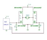
I'm need a current amplifier to boost a 12v signal that runs an actuator - leads change polarity to change direction with zero voltage being stopped. I tried an H bridge made up of cube relays, but it cycles too much and the relay life is about 16 hours. An FET H bridge looks like it would work, but I'm not sure my rotating polarity input signal is compatible - seems like normally it just uses an switch to select direction or a pwm signal to turn it on more often or less often. I now realize why I changed majors from EE to ME, but I still need a booster. It's likely I'm not thinking about this right and I'd appreciate any direction. I really didn't find an older post that fit my application so I thought I'd ask.
For those familiar with ag electronics I'm basically taking the output of a raven flow control console that normally runs a small motor controlled valve (1 amp max) and instead trying to control a 10amp linear actuator that controls a 6" ball valve. I have a pwm signal output available, but it isn't configurable to reverse the motor direction (only speed it up or slow it down).
thanks,
Pat