ravch
Newbie level 5

Bias: Vds = 3V, Vgs = 0.58V and Id = 60mA, Transistor: ATF541M4(avago), Frequency: 5.5 GHz
Capacitor at source port to make the transistor unstable.

Using the design rules to design the negative resistance oscillator, matching networks have been created using stubs. The matching networks are tuned so that the open loop gain condition is satisfied using OscTest. HB and transient simulators are used to obtain the oscillations. The schematic is shown below. If you zoom in you can find the exact lengths of the stubs. The microstrip lengths in the source ports are very big and capacitor in source port value is increased to 10pF. This is to maintain the loop gain greater than 1 and phase close to zero.

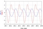
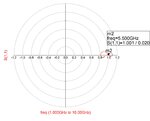
loopgain result
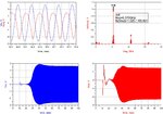
HB and tran results of the schematic are shown below.
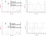

Now a layout is created(layout part for the bias is incomplete) and the layout component is used to check for the oscillations.


results of layout component
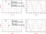

I tried with different values of stop time and maximum time step. But the output is still the same in transient.
I dont understand why it doesnt show the oscillations in transient even though there is harmonic result.
Capacitor at source port to make the transistor unstable.

Using the design rules to design the negative resistance oscillator, matching networks have been created using stubs. The matching networks are tuned so that the open loop gain condition is satisfied using OscTest. HB and transient simulators are used to obtain the oscillations. The schematic is shown below. If you zoom in you can find the exact lengths of the stubs. The microstrip lengths in the source ports are very big and capacitor in source port value is increased to 10pF. This is to maintain the loop gain greater than 1 and phase close to zero.

loopgain result

HB and tran results of the schematic are shown below.


Now a layout is created(layout part for the bias is incomplete) and the layout component is used to check for the oscillations.


results of layout component

I tried with different values of stop time and maximum time step. But the output is still the same in transient.
I dont understand why it doesnt show the oscillations in transient even though there is harmonic result.
Last edited:


