Continue to Site

Welcome to EDAboard.com

Welcome to our site! EDAboard.com is an international Electronics Discussion Forum focused on EDA software, circuits, schematics, books, theory, papers, asic, pld, 8051, DSP, Network, RF, Analog Design, PCB, Service Manuals... and a whole lot more! To participate you need to register. Registration is free. Click here to register now.

[SOLVED] need verification for lcd interface hardware connection using PIC16F877A

Status
Not open for further replies.

ccslearner

Junior Member level 1
Joined
Feb 1, 2013
Messages
19
Helped
2
Reputation
4
Reaction score
2
Trophy points
1,283
Location
India,tamilnadu
Activity points
1,445
hello edaboard viewers,

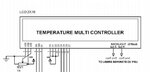
i am beginner of embedded system i make hardware connection of lcd interface using PIC16F877A mcu. i am not much more aware of hardware connection eventhough i make it and attached my hardware connection photo copy for your verification so please verify my connection and cite me any mistake if i made.


THANKS,,,,,,,,,,,,,,
lcddrawing.png
 

I just visit manufacturer web site and I'm shocked with dev board prices, and what you get for that.

:shock:


You can use email for technical support in bottom left corner of browser window.


Best regards,
Peter
 

make connection of VEE pin with 10K pot.

Also gnd the pin16 and make 5V on Pin15.

Rest of your connections looks an okay.
 

hi,

Like this, pin 15/16 only valid if your lcd has a backlight which, if you want it on, only needs 4.2v max , not 5v, so you must use a dropper resistor.
 

Attachments

  • 000013.jpg
    000013.jpg
    25 KB · Views: 79
This is my example:
LCD 20x2.jpg

See the connections!!!

Code in CCS of Main.c
Code:
#include<16f877a.h> 
#use delay(clock=4000000) 
#fuses HS,NOWDT,NOPROTECT,NOLVP 
#use rs232(baud=9600,xmit=PIN_C6,rcv=PIN_C7,parity=N,bits=8,ERRORS) 
#define LCD_ENABLE_PIN PIN_C0 
#define LCD_RS_PIN PIN_C1 
#define LCD_RW_PIN PIN_C2 
#define LCD_DATA4 PIN_D4 
#define LCD_DATA5 PIN_D5 
#define LCD_DATA6 PIN_D6 
#define LCD_DATA7 PIN_D7 
#include "lcd.c"

void main() 
{ 
   set_tris_d(0x00); 
   set_tris_c(0x00); 
   lcd_init(); 
   Delay_ms(100);
   lcd_putc("\fDISPLAY LINE 1");
   lcd_putc("\nDISPLAY LINE 2"); 
   while(TRUE) 
   { 

   } 
}

Code of lcd.c
Code:
///////////////////////////////////////////////////////////////////////////////
////                             LCD.C                                     ////
////                 Driver for common LCD modules                         ////
////                                                                       ////
////  lcd_init()   Must be called before any other function.               ////
////                                                                       ////
////  lcd_putc(c)  Will display c on the next position of the LCD.         ////
////                 \a  Set cursor position to upper left                 ////
////                 \f  Clear display, set cursor to upper left           ////
////                 \n  Go to start of second line                        ////
////                 \b  Move back one position                            ////
////              If LCD_EXTENDED_NEWLINE is defined, the \n character     ////
////              will erase all remanining characters on the current      ////
////              line, and move the cursor to the beginning of the next   ////
////              line.                                                    ////
////              If LCD_EXTENDED_NEWLINE is defined, the \r character     ////
////              will move the cursor to the start of the current         ////
////              line.                                                    ////
////                                                                       ////
////  lcd_gotoxy(x,y) Set write position on LCD (upper left is 1,1)        ////
////                                                                       ////
////  lcd_getc(x,y)   Returns character at position x,y on LCD             ////
////                                                                       ////
////  lcd_cursor_on(int1 on)   Turn the cursor on (on=TRUE) or off         ////
////              (on=FALSE).                                              ////
////                                                                       ////
////  lcd_set_cgram_char(w, *p)   Write a custom character to the CGRAM.   ////
////                                                                       ////
////                                                                       ////
////  CONFIGURATION                                                        ////
////  The LCD can be configured in one of two ways: a.) port access or     ////
////  b.) pin access.  Port access requires the entire 7 bit interface     ////
////  connected to one GPIO port, and the data bits (D4:D7 of the LCD)     ////
////  connected to sequential pins on the GPIO.  Pin access                ////
////  has no requirements, all 7 bits of the control interface can         ////
////  can be connected to any GPIO using several ports.                    ////
////                                                                       ////
////  To use port access, #define LCD_DATA_PORT to the SFR location of     ////
////  of the GPIO port that holds the interface, -AND- edit LCD_PIN_MAP    ////
////  of this file to configure the pin order.  If you are using a         ////
////  baseline PIC (PCB), then LCD_OUTPUT_MAP and LCD_INPUT_MAP also must  ////
////  be defined.                                                          ////
////                                                                       ////
////  Example of port access:                                              ////
////     #define LCD_DATA_PORT getenv("SFR:PORTD")                         ////
////                                                                       ////
////  To use pin access, the following pins must be defined:               ////
////     LCD_ENABLE_PIN                                                    ////
////     LCD_RS_PIN                                                        ////
////     LCD_RW_PIN                                                        ////
////     LCD_DATA4                                                         ////
////     LCD_DATA5                                                         ////
////     LCD_DATA6                                                         ////
////     LCD_DATA7                                                         ////
////                                                                       ////
////  Example of pin access:                                               ////
////     #define LCD_ENABLE_PIN  PIN_E0                                    ////
////     #define LCD_RS_PIN      PIN_E1                                    ////
////     #define LCD_RW_PIN      PIN_E2                                    ////
////     #define LCD_DATA4       PIN_D4                                    ////
////     #define LCD_DATA5       PIN_D5                                    ////
////     #define LCD_DATA6       PIN_D6                                    ////
////     #define LCD_DATA7       PIN_D7                                    ////
////                                                                       ////
///////////////////////////////////////////////////////////////////////////////
////        (C) Copyright 1996,2010 Custom Computer Services           ////
//// This source code may only be used by licensed users of the CCS C  ////
//// compiler.  This source code may only be distributed to other      ////
//// licensed users of the CCS C compiler.  No other use, reproduction ////
//// or distribution is permitted without written permission.          ////
//// Derivative programs created using this software in object code    ////
//// form are not restricted in any way.                               ////
///////////////////////////////////////////////////////////////////////////

#ifndef __LCD_C__
#define __LCD_C__

// define the pinout.
// only required if port access is being used.
typedef struct  
{                            // This structure is overlayed
   int1 enable;           // on to an I/O port to gain
   int1 rs;               // access to the LCD pins.
   int1 rw;               // The bits are allocated from
   int1 unused;           // low order up.  ENABLE will
   unsigned int     data : 4;         // be LSB pin of that port.
  #if defined(__PCD__)       // The port used will be LCD_DATA_PORT.
   unsigned int    reserved: 8;
  #endif
} LCD_PIN_MAP;

// this is to improve compatability with previous LCD drivers that accepted
// a define labeled 'use_portb_lcd' that configured the LCD onto port B.
#if ((defined(use_portb_lcd)) && (use_portb_lcd==TRUE))
 #define LCD_DATA_PORT getenv("SFR:PORTB")
#endif

#if defined(__PCB__)
   // these definitions only need to be modified for baseline PICs.
   // all other PICs use LCD_PIN_MAP or individual LCD_xxx pin definitions.
/*                                    EN, RS,   RW,   UNUSED,  DATA  */
 const LCD_PIN_MAP LCD_OUTPUT_MAP =  {0,  0,    0,    0,       0};
 const LCD_PIN_MAP LCD_INPUT_MAP =   {0,  0,    0,    0,       0xF};
#endif

////////////////////// END CONFIGURATION ///////////////////////////////////

#ifndef LCD_ENABLE_PIN
   #define lcd_output_enable(x) lcdlat.enable=x
   #define lcd_enable_tris()   lcdtris.enable=0
#else
   #define lcd_output_enable(x) output_bit(LCD_ENABLE_PIN, x)
   #define lcd_enable_tris()  output_drive(LCD_ENABLE_PIN)
#endif

#ifndef LCD_RS_PIN
   #define lcd_output_rs(x) lcdlat.rs=x
   #define lcd_rs_tris()   lcdtris.rs=0
#else
   #define lcd_output_rs(x) output_bit(LCD_RS_PIN, x)
   #define lcd_rs_tris()  output_drive(LCD_RS_PIN)
#endif

#ifndef LCD_RW_PIN
   #define lcd_output_rw(x) lcdlat.rw=x
   #define lcd_rw_tris()   lcdtris.rw=0
#else
   #define lcd_output_rw(x) output_bit(LCD_RW_PIN, x)
   #define lcd_rw_tris()  output_drive(LCD_RW_PIN)
#endif

// original version of this library incorrectly labeled LCD_DATA0 as LCD_DATA4,
// LCD_DATA1 as LCD_DATA5, and so on.  this block of code makes the driver
// compatible with any code written for the original library
#if (defined(LCD_DATA0) && defined(LCD_DATA1) && defined(LCD_DATA2) && defined(LCD_DATA3) && !defined(LCD_DATA4) && !defined(LCD_DATA5) && !defined(LCD_DATA6) && !defined(LCD_DATA7))
   #define  LCD_DATA4    LCD_DATA0
   #define  LCD_DATA5    LCD_DATA1
   #define  LCD_DATA6    LCD_DATA2
   #define  LCD_DATA7    LCD_DATA3
#endif

#ifndef LCD_DATA4
#ifndef LCD_DATA_PORT
   #if defined(__PCB__)
      #define LCD_DATA_PORT      0x06     //portb
      #define set_tris_lcd(x)   set_tris_b(x)
   #else
     #if defined(PIN_D0)
      #define LCD_DATA_PORT      getenv("SFR:PORTD")     //portd
     #else
      #define LCD_DATA_PORT      getenv("SFR:PORTB")     //portb
     #endif
   #endif   
#endif

#if defined(__PCB__)
   LCD_PIN_MAP lcd, lcdlat;
   #byte lcd = LCD_DATA_PORT
   #byte lcdlat = LCD_DATA_PORT
#elif defined(__PCM__)
   LCD_PIN_MAP lcd, lcdlat, lcdtris;
   #byte lcd = LCD_DATA_PORT
   #byte lcdlat = LCD_DATA_PORT
   #byte lcdtris = LCD_DATA_PORT+0x80
#elif defined(__PCH__)
   LCD_PIN_MAP lcd, lcdlat, lcdtris;
   #byte lcd = LCD_DATA_PORT
   #byte lcdlat = LCD_DATA_PORT+9
   #byte lcdtris = LCD_DATA_PORT+0x12
#elif defined(__PCD__)
   LCD_PIN_MAP lcd, lcdlat, lcdtris;
   #word lcd = LCD_DATA_PORT
   #word lcdlat = LCD_DATA_PORT+2
   #word lcdtris = LCD_DATA_PORT-0x02
#endif
#endif   //LCD_DATA4 not defined

#ifndef LCD_TYPE
   #define LCD_TYPE 2           // 0=5x7, 1=5x10, 2=2 lines
#endif

#ifndef LCD_LINE_TWO
   #define LCD_LINE_TWO 0x40    // LCD RAM address for the second line
#endif

#ifndef LCD_LINE_LENGTH
   #define LCD_LINE_LENGTH 20
#endif

unsigned int8 const LCD_INIT_STRING[4] = {0x20 | (LCD_TYPE << 2), 0xc, 1, 6};
                             // These bytes need to be sent to the LCD
                             // to start it up.

unsigned int8 lcd_read_nibble(void);

unsigned int8 lcd_read_byte(void)
{
   unsigned int8 low,high;

 #if defined(__PCB__)
   set_tris_lcd(LCD_INPUT_MAP);
 #else
  #if (defined(LCD_DATA4) && defined(LCD_DATA5) && defined(LCD_DATA6) && defined(LCD_DATA7))
   output_float(LCD_DATA4);
   output_float(LCD_DATA5);
   output_float(LCD_DATA6);
   output_float(LCD_DATA7);
  #else
   lcdtris.data = 0xF;
  #endif
 #endif
        
   lcd_output_rw(1);
   delay_cycles(1);
   lcd_output_enable(1);
   delay_cycles(1);
   high = lcd_read_nibble();
      
   lcd_output_enable(0);
   delay_cycles(1);
   lcd_output_enable(1);
   delay_us(1);
   low = lcd_read_nibble();
      
   lcd_output_enable(0);

 #if defined(__PCB__)
   set_tris_lcd(LCD_OUTPUT_MAP);
 #else
  #if (defined(LCD_DATA4) && defined(LCD_DATA5) && defined(LCD_DATA6) && defined(LCD_DATA7))
   output_drive(LCD_DATA4);
   output_drive(LCD_DATA5);
   output_drive(LCD_DATA6);
   output_drive(LCD_DATA7);
  #else
   lcdtris.data = 0x0;
  #endif
 #endif

   return( (high<<4) | low);
}

unsigned int8 lcd_read_nibble(void)
{
  #if (defined(LCD_DATA4) && defined(LCD_DATA5) && defined(LCD_DATA6) && defined(LCD_DATA7))
   unsigned int8 n = 0x00;

   /* Read the data port */
   n |= input(LCD_DATA4);
   n |= input(LCD_DATA5) << 1;
   n |= input(LCD_DATA6) << 2;
   n |= input(LCD_DATA7) << 3;
   
   return(n);
  #else
   return(lcd.data);
  #endif
}

void lcd_send_nibble(unsigned int8 n)
{
  #if (defined(LCD_DATA4) && defined(LCD_DATA5) && defined(LCD_DATA6) && defined(LCD_DATA7))
   /* Write to the data port */
   output_bit(LCD_DATA4, bit_test(n, 0));
   output_bit(LCD_DATA5, bit_test(n, 1));
   output_bit(LCD_DATA6, bit_test(n, 2));
   output_bit(LCD_DATA7, bit_test(n, 3));
  #else      
   lcdlat.data = n;
  #endif
      
   delay_cycles(1);
   lcd_output_enable(1);
   delay_us(2);
   lcd_output_enable(0);
}

void lcd_send_byte(unsigned int8 address, unsigned int8 n)
{
  #if defined(__PCB__)
   set_tris_lcd(LCD_OUTPUT_MAP);
  #else
   lcd_enable_tris();
   lcd_rs_tris();
   lcd_rw_tris();
  #endif

   lcd_output_rs(0);
   while ( bit_test(lcd_read_byte(),7) ) ;
   lcd_output_rs(address);
   delay_cycles(1);
   lcd_output_rw(0);
   delay_cycles(1);
   lcd_output_enable(0);
   lcd_send_nibble(n >> 4);
   lcd_send_nibble(n & 0xf);
}

#if defined(LCD_EXTENDED_NEWLINE)
unsigned int8 g_LcdX, g_LcdY;
#endif

void lcd_init(void) 
{
   unsigned int8 i;

 #if defined(__PCB__)
   set_tris_lcd(LCD_OUTPUT_MAP);
 #else
  #if (defined(LCD_DATA4) && defined(LCD_DATA5) && defined(LCD_DATA6) && defined(LCD_DATA7))
   output_drive(LCD_DATA4);
   output_drive(LCD_DATA5);
   output_drive(LCD_DATA6);
   output_drive(LCD_DATA7);
  #else
   lcdtris.data = 0x0;
  #endif
   lcd_enable_tris();
   lcd_rs_tris();
   lcd_rw_tris();
 #endif

   lcd_output_rs(0);
   lcd_output_rw(0);
   lcd_output_enable(0);
    
   delay_ms(15);
   for(i=1;i<=3;++i)
   {
       lcd_send_nibble(3);
       delay_ms(5);
   }
   
   lcd_send_nibble(2);
   delay_ms(5);
   for(i=0;i<=3;++i)
      lcd_send_byte(0,LCD_INIT_STRING[i]);

  #if defined(LCD_EXTENDED_NEWLINE)
   g_LcdX = 0;
   g_LcdY = 0;
  #endif
}

void lcd_gotoxy(unsigned int8 x, unsigned int8 y)
{
   unsigned int8 address;
   
   if(y!=1)
      address=LCD_LINE_TWO;
   else
      address=0;
     
   address+=x-1;
   lcd_send_byte(0,0x80|address);

  #if defined(LCD_EXTENDED_NEWLINE)
   g_LcdX = x - 1;
   g_LcdY = y - 1;
  #endif
}

void lcd_putc(char c)
{
   switch (c)
   {
      case '\a'   :  lcd_gotoxy(1,1);     break;

      case '\f'   :  lcd_send_byte(0,1);
                     delay_ms(2);
                    #if defined(LCD_EXTENDED_NEWLINE)
                     g_LcdX = 0;
                     g_LcdY = 0;
                    #endif
                     break;

     #if defined(LCD_EXTENDED_NEWLINE)
      case '\r'   :  lcd_gotoxy(1, g_LcdY+1);   break;
      case '\n'   :
         while (g_LcdX++ < LCD_LINE_LENGTH)
         {
            lcd_send_byte(1, ' ');
         }
         lcd_gotoxy(1, g_LcdY+2);
         break;
     #else
      case '\n'   : lcd_gotoxy(1,2);        break;
     #endif
     
      case '\b'   : lcd_send_byte(0,0x10);  break;
     
     #if defined(LCD_EXTENDED_NEWLINE)
      default     : 
         if (g_LcdX < LCD_LINE_LENGTH)
         {
            lcd_send_byte(1, c);
            g_LcdX++;
         }
         break;
     #else
      default     : lcd_send_byte(1,c);     break;
     #endif
   }
}
 
char lcd_getc(unsigned int8 x, unsigned int8 y)
{
   char value;

   lcd_gotoxy(x,y);
   while ( bit_test(lcd_read_byte(),7) ); // wait until busy flag is low
   lcd_output_rs(1);
   value = lcd_read_byte();
   lcd_output_rs(0);
   
   return(value);
}

// write a custom character to the ram
// which is 0-7 and specifies which character array we are modifying.
// ptr points to an array of 8 bytes, where each byte is the next row of
//    pixels.  only bits 0-4 are used.  the last row is the cursor row, and
//    usually you will want to leave this byte 0x00.
void lcd_set_cgram_char(unsigned int8 which, unsigned int8 *ptr)
{
   unsigned int i;

   which <<= 3;
   which &= 0x38;

   lcd_send_byte(0, 0x40 | which);  //set cgram address

   for(i=0; i<8; i++)
   {
      lcd_send_byte(1, *ptr++);
   }
  
   #if defined(LCD_EXTENDED_NEWLINE)
    lcd_gotoxy(g_LcdX+1, g_LcdY+1);  //set ddram address
   #endif
}

void lcd_cursor_on(int1 on)
{
   if (on)
   {
      lcd_send_byte(0,0x0F);           //turn LCD cursor ON
   }
   else
   {
      lcd_send_byte(0,0x0C);           //turn LCD cursor OFF
   }
}

#endif
 
thanks briez actually my lcd don't have 15 and 16 pins its only 14 pin LCD ,can you sure for power up my development board ????
 

Yes, you must connect 1st pin of your lcd to Ground and 2nd pin with VCC.

if you are not using 15th and 16th pin then you don't have to connect 10K pot on 3rd pin.

And data pins seems an okay connected so try to check your connectivity through multimeter and if its as you defined in picture then it should work best...
 

Status
Not open for further replies.

Similar threads

Part and Inventory Search

Welcome to EDABoard.com

Sponsor

Back
Top