Welcome to our site! EDAboard.com is an international Electronics Discussion Forum focused on EDA software, circuits, schematics, books, theory, papers, asic, pld, 8051, DSP, Network, RF, Analog Design, PCB, Service Manuals... and a whole lot more! To participate you need to register. Registration is free. Click here to register now.
Any idea what its purpose is? Maybe a picture of the entire PCB would help with a description of what product it is?
Is it near a power source? Near a microcontroller? Maybe a transceiver for comms? What I am trying to say is put the IC in context.
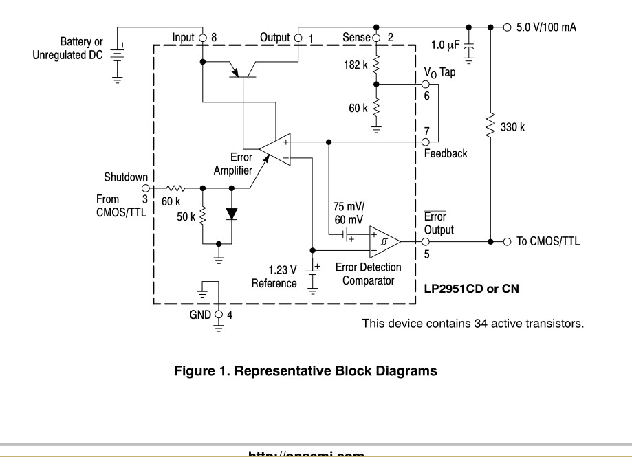
looking at IC's map (shown above) I see electrolytic capacitor which signed as a "1,23 V reference".
-probably somebody knows how it works? Do they really have electrolytic capacitor inside?
-Then one thought comes in my mind...
-probably, they should have quite restricted frist of application . So I suspicion they begin to die of their capaсitors after 7-10 years of running.
The symbol to which you refer is actually a battery cell symbol, not an electrolytic capacitor symbol, which signifies the 1.23 V voltage reference.
As the diagram indicates, "Representative Block Diagram," which generalizes the internal function of the device, rather than actual specifics of it's design.
expanding on that.... just as it doesn't have an electrolytic capcitor inside, it doesn't have a battery either. It is diagramatic of a reference voltage, a stable voltage derived from the input at pin 8.
The "Error Amplifier" compares it with the voltage at pin 7 to control the output voltage. The manufacturer provides a built-in divider available at pin 6 for the convenience of use when 5V is needed but by breaking the connection to pin 7 you can use your own external resistors to set other voltages. If you calculate the voltage at pin 6 from the resistor values you will note it is also ~1.23V.
This site uses cookies to help personalise content, tailor your experience and to keep you logged in if you register.
By continuing to use this site, you are consenting to our use of cookies.

")