Continue to Site

Welcome to EDAboard.com

Welcome to our site! EDAboard.com is an international Electronics Discussion Forum focused on EDA software, circuits, schematics, books, theory, papers, asic, pld, 8051, DSP, Network, RF, Analog Design, PCB, Service Manuals... and a whole lot more! To participate you need to register. Registration is free. Click here to register now.

Need help with datasheet for my crystals

Status
Not open for further replies.

patrickian01

Member level 1
Joined
May 17, 2013
Messages
35
Helped
0
Reputation
0
Reaction score
0
Trophy points
1,286
Activity points
1,626
Hi,

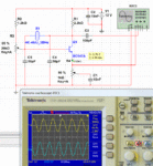
So I've been trying to build an oscillator using crystal resonators and I'm familiar with the crystal equivalent circuit being a series RLC in parallel with a capacitor and I've been told that the values of the components in the equivalent circuit is found on it's datasheet. The problem is, I couldn't find the datasheet for my crystals and I don't even know it's manufacturer. The crystals are labeled as follows:

39.168 UNI 97 - A (this is a 3rd overtone crystal, i tried using it on an IC oscillator and it works on the 3rd overtone)
72.673 UNI 7A (3rd overtone crystal)
46.475 UNI (3rd overtone crystal)
63.3333 UNI 7A (3rd overtone)

It worked on an IC oscillator using 74LS04 and produced square waves. I'm trying to do it with transistors so i get a sine wave, however, first things first, i need the datasheet for the crystals. Any help is much appreciated.
 

If you have access to a network analyzer, you can determine all these parameters yourself.
Alternatively, you can use the method presented here to get a fairly accurate model: https://www.giangrandi.ch/electronics/crystalfilters/xtaltest.html
You still need some basic equipment like a scope, signal generator and RF voltmeter.
 

Crystal manufacturers don't usually provide what are known as the motional parameters; you have to measure them.

There are several ways, the simplest probably being the G3UUR method that Google will find for you.

This method requires the construction of a simple oscillator and the use of a frequency counter. Here is my build;

https://i39.tinypic.com/t7h6oh.jpg

It does also require the accurate measurement of a capacitor of about 30 pF.

For an excellent paper on crystal measurement go here;

**broken link removed**

and find "Crystal Parameters" about half-way down.

I have used all of the methods described; the method you can use will depend upon the equipment you have available. The G3UUR method is as good as any provided the oscillator is carefully constructed.

The method you use will depend upon the equipment you have available.

Incidentally, you don't usually require the crystal motional parameters for oscillators; they are required for design of good crystal filters.
 

Incidentally, you don't usually require the crystal motional parameters for oscillators; they are required for design of good crystal filters.

Sometimes it is good to know the value of Rs, especially for low frequency crystals (where Rs can be high in value) to make sure your osc design generate enough negative resistance to cancel out Rs.
 
Last edited:

There are spectrum analyzers available at school but i can't get to them until monday, so there would be no way that i could do the suggestion as stated above. signal generators and oscilloscopes are available at school as well although i'm not sure about the highest frequency that it can generate but i will take a look at it on monday. I'm not sure about an RF voltmeter though.

I can't get my oscillator design to work both on breadboard and on simulation (multisim). I don't know what I'm doing wrong. here's the circuit that I'm using:
oscillator.PNG
The circuit came from this video: https://www.youtube.com/watch?v=VMoIAIC5sOU
he got it to work and i tried playing around with the potentiometers with no luck. if you spot something wrong, do chime me in. I get CE amplifiers however, It becomes really really hard when I put crystals in. anyway, thank you for the help.
 

let me rephrase and clarify some of my questions. i found another circuit and decided to simulate it. this is a schematic of the circuit along with some of the results.
Pierce Oscillator BJT.PNG
this is a pierce oscillator using a BJT and as the results showed, it's not exactly what i wanted. here is where my questions come in.
first of all, is it even possible to oscillate the crystal at that frequency and produce a sine wave?
i know that some of the components are of the wrong values and my question is, what is/are the purposes of each component in the circuit?
how are they mathematically computed and what do they actually do to make the circuit oscillate?
what important parameters do i take into consideration? the barkhausen criteria? i know of it, but how do i know that i satisfy it?

Here is another picture of a pierce oscillator using an FET along with the results of the simulation. again, the same questions apply.
Pierce Oscillator FET.PNG

sorry if i sound inexperienced here, I am inexperienced and I read a lot about crystal oscillators on books but all they do is explain the circuit equivalent of a crystal and series/parallel resonance and give sample circuits but don't explain them in detail. I don't pretty much understand everything myself, which is why I'm asking for help. Any help is much appreciated. :)
 

It appears that the person in the video doesn't understand all the criteria for oscillation regarding a pierce circuit. His circuit oscillates by accident due to the long connecting wires which creates enough stray capacitance (and needed extra phase shift) in the circuit to oscillate.

Basically, for oscillation to happen you need the inverting amplifier, and then you need enough phase shift to make up the other 180° to get you back at 0° or 360°.
To get the last 180°, you need two phase shift combinations. One is the output driving impedance of the amplifier connected to C4, and the other one is made up by the internal resistor of the crystal Rs and C5. I have set R3 to get about 1/3 of the supply voltage on the emitter, which is a good bias point.

The loaded Q of the circuit (high loaded Q gives better frequency stability) will increase by increasing the values of C4 and C5, but so will the insertion loss from the crystal as a result. With increased loaded Q, you will need more loop gain for oscillations to start.
 

Attachments

  • pierce1.gif
    pierce1.gif
    86.3 KB · Views: 116
Last edited:

Thank you very much for the reply. I will definately try your circuit. I have some questions though, how did you get the values for the capacitors? what factors did you consider? Assuming that I would be using other crystals, how do I know what values of the capacitors and resistors i should use?

I'm really sorry if i don't know much here. This is probably my weakest subject and I would really like to learn how they work. again, thank you very much for the reply. :)
 

Here is some notes **broken link removed**
I use a different method but you need access to a network analyzer to verify phase shift and open loop gain.

An example is shown below looking at the gain/phase in a colpitts design.

With a pierce design you need to know or be able to measure Rs of the crystal. Your starting point is then to have the loading capacitance's resistance value about 0.2*Rs. The problem is that you need a lot of gain (about 29dB) to overcome these large insertion losses. You also need a low enough output impedance driving into Rs. At higher frequencies, you need to add an emitter follower to be able to drive the lower Rs of the crystal. A compromise is often made by inserting extra resistance in series to make it easier for the amplifier to drive. When this happens then the shunt capacitor value decreases to compensate for gain loss. It is difficult to get enough gain above 20MHz without a LC tank in the amplifier output. For this reason pierce designs will be normally limited to well below 20MHz. At very low frequencies you need an amplifier with a FET input as not to load the high Rs value of the crystal.
 

Attachments

  • VNA.jpg
    VNA.jpg
    348.4 KB · Views: 107
Last edited:

Okay, I've decided to take it step by step beginning first with a transistor amplifier (Common Emitter)
The Circuit Looks like this:
CE Amp.PNG
ignore the values in there first and have a look at my computations below (since multisim won't allow me to place components without values)

Since V1 is 6V, if I want a voltage drop across R3 to be 3V and Ic (current through R3) to be 1mA, then R3 = (V1 - 3V)/1mA = 3k ohms
Since Ic ~ Ie (Current through R4), assuming that R4 = 100 ohms, Ve (voltage accross R4) = Ie*R4 = 0.1V
Assuming that Vbe (base-emitter voltage is 0.7V) and assuming that B (beta) = 100, Zin (input impedance) = B*R4 = 10k ohms
Calculations with R1 and R2 could be ignored since I will be using crystals (AC), am i right? If so, what values could I use for R1 and R2? and I understand that the crystal goes through the collector and the base, If the crystal is now added, what other things do i consider and where do i place the capacitors to take into account the phase shifts that i need?

One more thing, in the circuit that showed earlier with the 3MHz crystal, how did you know the values of the capacitors that the crystal needed would be 2 56pF capacitors? and what is the purpose of adding the 10nF bypass to the voltage source? :)
 
Last edited:

Your attachment does not work. It reports an invalid link.
 

I just had an idea... so, i built an oscillator using inverters with the 74LS04 IC and it produces square waves as said by the oscilloscope although they appear to be sine waves. since the crystal acts as a filter for a specific frequency, what if I use the same crystal on a transistor oscillator and use the square waves generated by the 74LS04 IC to kickstart oscillation in the transistor, similar to what was done here: **broken link removed**

i tried the circuit using different crystals and it works, although the Vp-p decreases overtime (i suspect that by the 1s mark, it would have gone down to near 0), that is why i would like to use transistors to give it the needed gain to sustain oscillation. do you think it would work? :)

update---
So, i tried this configuration and got it to work!
here's what the circuit looks like:
kickstart using square wave generator.PNG
i first connected the function generator and then opened the switch and it started to oscillate at sine waves even if the function gen fed square waves to the circuit. the only problem is, it started to die out the moment it started oscillating and at around 0.01ms, it's nearly in the microvolts level. any idea on how i can keep it oscillating at probably the millivolt level?
 
Last edited:

Like I mentioned before
It is difficult to get enough gain above 20MHz without a LC tank in the amplifier output.
at 20MHz and above you will struggle to get enough loop gain to sustain oscillations. you can try and put an LC tank as the collector load.
 

and the LC tank should be tuned to the frequency of the crystal right? characterized by the equation:

f = 1 / (2*pi) * (sqrt(L*C))

following the equation and assuming that I have a fixed 10000nH / 10microH inductor, for a 25MHz oscillator, I should have a capacitor with a value of 4.05pF. I can't get to a computer with multisim right now but I'm going to try probably tomorrow. thanks for the help and will keep you posted. :)
 

So i decided to go back and check my oscillators using the 74LS04 inverters and found out that the output was actually closer to a triangle wave than a square wave. I also inspected the FFT and found out that it is indeed a triangle wave with 2-3 harmonics, the strongest of which is at most half the strength of the fundamental frequency. the circuit looks like this:
IC.PNG
i could probably get a snapshot of the FFT and the wave produced by tomorrow so i can also upload it. I've also been trying to adjust the feedback potentiometer so that the gain would be just right to produce sine waves, however, the closest i can get to a sine wave is a triangle wave that LOOKS LIKE a sine wave but FFT suggests that there are odd harmonics, probably up to the 3rd odd harmonic. Is there a way to smoothen it further down to a sine wave so that i wouldn't resort to transistor oscillators? by the way, the output is 20mVp-p and assuming that it has already gone through impedance matching, is it already good enough to transmit via a quarter wave monopole and i would only transmit it for a few meters?
 

Status
Not open for further replies.

Similar threads

Part and Inventory Search

Welcome to EDABoard.com

Sponsor

Back
Top