Continue to Site

Welcome to EDAboard.com

Welcome to our site! EDAboard.com is an international Electronics Discussion Forum focused on EDA software, circuits, schematics, books, theory, papers, asic, pld, 8051, DSP, Network, RF, Analog Design, PCB, Service Manuals... and a whole lot more! To participate you need to register. Registration is free. Click here to register now.

Need help with a schematic

Status
Not open for further replies.

raf23

Newbie level 5
Joined
Jun 24, 2010
Messages
8
Helped
0
Reputation
0
Reaction score
0
Trophy points
1,281
Location
india
Activity points
1,370
Hi
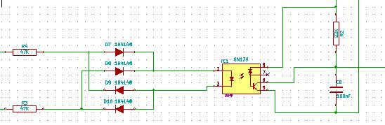
I have a circuit diagram which i believe is for a zero crossing detection. if it is of zero cross detection ,can any one tell whether it is VZC or CZC ? Also it would be helpful if someone can tell the waveform at the collector pin of transistor with respect to ac waveform. ckt diagram is attached here

zerocrossmodf.png
 

It does not appear to be a zero crossing detector.
It seems to be a voltage regulator and 50Hz AC-derived pull-down pulser for a microcontroller mcu.

The AC input is appled to either pins 1 or 3 relative to pin 2. This is so as to be able to insert the connector J1 either way around. The regulator U1, further isolated by D8, uses smoothed 1/2wave rectified power at input, and delivers 5V.

The presence of power via D7, delivers a turn-on bias to the transistor Q2 with every positive half-wave of the AC. This is divided by R1 and R2. The AC has to go through 2 diodes before the divider.

I expect the end result would be a 50Hz square wave(ish) pulse train at the collector of Q2 provided the output is biased up externally. It is a stream of pull-down pulses.
 

It's a regulated power supply with a voltage zero crossing detector. The zero point won't be very well defined in this circuit but it will occur once per half cycle.
As it stands there is no output waveform, to make it work you will need an additional resitor from the "to mcu" connection to the MCUs supply line (probably the +5V from the regulator). With the resistor fitted you should get a waveform which is normally low but goes high when either the positive or negative half cycles of the AC are less than about +/- 1.2 Volts. So when the falling input goes below 1.2V the output goes high and when the rising input exceeds 1.2V it goes low again.

Brian.
 
  • Like
Reactions: raf23

    raf23

    Points: 2
    Helpful Answer Positive Rating
It's not really feasible to predict exactly what kind of rise/fall delay the circuit will have, since it's so nonlinear, and especially since the input amplitude is just 16V. The value of C10 will also have a great effect on the timings.

A more precise way would be to use a comparator with both of the secondary (or even primary) ends connected (with some attenuators and clamps for protection).
 

It's a regulated power supply with a voltage zero crossing detector. The zero point won't be very well defined in this circuit but it will occur once per half cycle.
Brian.

A quick try with the (free) LTSpice. The zero crossing is kind of mid-pulse, not defined by a pulse transition edge. I used a general purpose silicon diode. I made the Vpeak = 16*sqrt(2) = 22.6V, because I took 16_0_16 to mean 16V RMS from each of two windings about a centre tapped 50Hz transformer output.

zerocross_sim.png

Hope this helps..
 
  • Like
Reactions: raf23

    raf23

    Points: 2
    Helpful Answer Positive Rating
It's a regulated power supply with a voltage zero crossing detector. The zero point won't be very well defined in this circuit but it will occur once per half cycle.
As it stands there is no output waveform, to make it work you will need an additional resitor from the "to mcu" connection to the MCUs supply line (probably the +5V from the regulator). With the resistor fitted you should get a waveform which is normally low but goes high when either the positive or negative half cycles of the AC are less than about +/- 1.2 Volts. So when the falling input goes below 1.2V the output goes high and when the rising input exceeds 1.2V it goes low again.

Brian.

Thanks ..how much error will come into it if i take any edge for zero crossing>
 

In an ideal zero crossing detector the output changes at exactly the point where the input polarity changes, the zero as positive changes from positive to negative and again as it changes back. So you get two pulses per cycle.

The problem with the design you show is that instead of detecting zero volts, it detects anything less than about 1.2V. On a high AC voltage this may be perfectly acceptable but when it's as low as 16V it becomes a sizeable part of the cycle length. The cure depends on exatly what you need the signal for, if it's just to provide a pulse at AC rate, for example to operate a digital clock, you can use the existing circuit. If you are doing something that needs critical timing such as Triac control it would work better if you could more precisely find the zero point.

The simples way to make it more accurate is to eliminate one of the voltage drops. If you short out D7, remove C2 and increase the values of R1 to 1K and R2 to 47K it will significantly increase the accuracy.

Tell us what the application is and we can advise if firther changes are needed.

Brian.

Thanks Brian.. I'm using it for controlling triac... actually this hardware works fine in the existing i just want to experiment with the software where pic micro controller is used to fire the triac...AC that comes to traic portion is not 16-0-16 its 230v/50Hz. so would this be a problem ?
 

If you are using that schematic as it is but with 230V at the input I would build yourself a blast shelter before switching on! The principle for the zero crossing can be used though but you must realize that it provides no AC isolation so all parts of it would be dangerous to touch and you couldn't connect it to any other equipment. A better system is to use an isolated signal using an opto-coupler. I'm working on a project at the moment that uses this kind of circuit so I've copied a section of the schematic for you. The connections on the left are 230V AC in, the resistors on the left are both 47K, the diodes are 1N4148, the opto-coupler is a 6N139. The connection at the top is 5V from a PIC supply rail and the pull-up resistor is 22K. Tou can leave the capacitor out for your application. Choose 47K resistors rated at 250V or more, some small resistors are not rated for high voltage use.


This will give you a far more accurate timing pulse than your schematic and it provides a safety isolation to several KV as well. the output will go high at each zero crossing.

Brian.

Thanks for your concern Brian..But I never thought of giving 230v where 16-0-16 is using. what I meant is that 16-0-16 is derived from the 230v line and 230v is going to the triac part . Please have a look at the image attachedView attachment firing triac.bmp
 

Status
Not open for further replies.

Similar threads

Part and Inventory Search

Welcome to EDABoard.com

Sponsor

Back
Top