guerillary
Newbie level 4

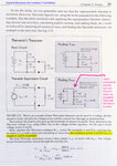
I just started learning electronics and am completely stumped by a circuit analysis example using Thevenin's Theorem on page 77 of "Practical Electronics for Inventors", Third Edition.
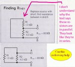
In the attached book excerpt, the circuit diagram looks to me as if resistors R1 and R2 are in series, however the description of proper analysis (highlighted) says the resistors are in parallel.
Am hoping someone here can please help me understand why the resistors are in parallel as opposed to in series.
THANKS!


