Continue to Site

Welcome to EDAboard.com

Welcome to our site! EDAboard.com is an international Electronics Discussion Forum focused on EDA software, circuits, schematics, books, theory, papers, asic, pld, 8051, DSP, Network, RF, Analog Design, PCB, Service Manuals... and a whole lot more! To participate you need to register. Registration is free. Click here to register now.

Need help to convert an industrial servo (1/2 HP . 220) into a DC

Status
Not open for further replies.

jovimon

Newbie level 6
Newbie level 6
Joined
Aug 23, 2013
Messages
11
Helped
0
Reputation
0
Reaction score
0
Trophy points
1
Visit site
Activity points
80
HI: have a servomotor of about ½ hp (220), and want to turn it into a DC for a Eolic turbine application. I just have basics in electronics, and may be you could give a hand to wire it up for test it.
This motor comes from ZOJE SEWING MACHINE CO. Probably they are not the makers. They use it with their sewing machines. Down is the information I could gather. I´m including some pics that could help a little. It comes with two main cables: one with 4 leades (black, green, gray and brown), the second (Black, red, yellow, green and blue).
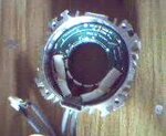
Converted_file_395e7a27.jpgConverted_file_7077646e[1].JPG

It seems it manages nine diferent speeds

Model: PS-21
Voltage (AC) 220 V
Speed: 5500 RPM
Power: 380 W
Torque Moment: 1 N.M.
Working System: SI

Any help will be highly appreciated. Regards
 

You are only showing the stator...what does the rotor look like? Is it permanently magnetized? Does it have slots?

Other question...is it only two wires coming out from the stator? Does the green circular board contain any type of electronic components?
 
You are only showing the stator...what does the rotor look like? Is it permanently magnetized? Does it have slots?

Other question...is it only two wires coming out from the stator? Does the green circular board contain any type of electronic components?

Thank you ST for answer: Here I´m including a pic of the rotor, which is made of permanent magnets (Neodymium I guess). As you can see it has 8 little slots in the middle.
Just two main cables (one with 4 leads, the other with 5 leads), come out from the stator. The green circular board is not easy to remove, but from what I can see, it has three (3) transistors under, and hid between coils.

rotor.JPG
 

The "transistors" most likely are hall sensors.

This motor is most likely a three-phase brushless motor.

Do the following:
1- Reassemble the motor
2- Have someone help you rotate the shaft while you take voltage measurements between the leads. Concentrate ONLY on the thicker wires, which must be the ones feeding the coils. The thinner ones must be the hall sensors.
3- Find the wires which produce a voltage between them as the shaft is rotated. NOTE: all of the BLDCs I've ever seen are 3 phase delta connected, so only 3 wires should produce voltage...but they could be wye connected and thus there will be 4 power wires.
4- Feed the those voltage producing wires to a three phase rectifier, and you'll have your DC output.
 
you cannot do that , you donot have a cummutator , and how would you install teh brushes !!!
 

If the motor is a BLDC, which I think it is, it doesn't need a conmutator. The field is permanent, created by the magnet in the rotor.
The output voltage will be induced on the stator windings.

This is not speculation or opinion. I have right now, as I type this, a BLDC motor in front of me. If I turn the shaft I see the AC voltage on the scope.
 
The "transistors" most likely are hall sensors.

This motor is most likely a three-phase brushless motor.

Do the following:
1- Reassemble the motor
2- Have someone help you rotate the shaft while you take voltage measurements between the leads. Concentrate ONLY on the thicker wires, which must be the ones feeding the coils. The thinner ones must be the hall sensors.
3- Find the wires which produce a voltage between them as the shaft is rotated. NOTE: all of the BLDCs I've ever seen are 3 phase delta connected, so only 3 wires should produce voltage...but they could be wye connected and thus there will be 4 power wires.
4- Feed the those voltage producing wires to a three phase rectifier, and you'll have your DC output.

I Find AC voltage between all possible combination of wires (Black, Green, Brown, Yellow/Green). I notice that all combinations with wire Y/G are sensibly of lower voltage than the rest; in fact part of this wire comes out and is screwed to the motor housing (so it must be one ground … I guess). I don´t know what to do at this point.

I´m stepping forward to look for a three phase rectifier and I see a lot of different kinds, so I´d like a recommendation please.
 

Its a wye connection.
Use a diode on each output then.

Sorry for this stupid question (as I told you I just have some basics in electronics). I have four leads coming out of the motor, and all rectifier circuits just three coming in, so which wires to choose (between Black, Green, Brown Yellow/green)?. I have in mind the next circuit.

http://hackedgadgets.com/wp-content/uploads/2010/10/3-phase-bridge-rectifier.png

One last question: As a servo it can reach 5500 rpm, Is at this speed (working as DC) when it can reach the maximum output power?
Thanks ST
 

That rectfier circuit is fine, just leave the yellow/green open.
Yes, at maximum RPM there will be maximum voltage.
 
That rectfier circuit is fine, just leave the yellow/green open.
Yes, at maximum RPM there will be maximum voltage.

Hi S.T.: I´m back again with a couple of questions, since I don´t want to wrong choosing the most adequate rectifier for this application. ¿Is 380 Watts the maximum output power that I can expect from the converted DC motor?. ¿the chosen rectifier must fit to this range (380 W) + a safety factor (may be 1.5, that is 570 Watt)?

Thanks
 

Rectifiers are not selected by power, but by maximum reverse voltage and maximum forward current.
Choose a 600V, 3 Amp device.
 
HI S.T.: Back again. I´m considering using AC current too, for some uses, out of this generator at 220V and 110V; for the first case (220V), ¿ Is just a matter of picking two of the three leads, and for 110V, using a transformer to take it from 220V to 110V? If so, What would be the range (in amps) for the transformer?
 

I'm afraid that won't be practical. Output voltage and frequency will change with with rotor speed.
 
Status
Not open for further replies.

Similar threads

Part and Inventory Search

Welcome to EDABoard.com

Sponsor

Back
Top