Welcome to our site! EDAboard.com is an international Electronics Discussion Forum focused on EDA software, circuits, schematics, books, theory, papers, asic, pld, 8051, DSP, Network, RF, Analog Design, PCB, Service Manuals... and a whole lot more! To participate you need to register. Registration is free. Click here to register now.
Sure - that'll certainly work... within limits. Let me explain:
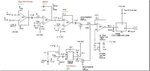
Depending on how much bandwidth you want to jam at any one time, "swept VCO" designs such as this have limitations imposed by the analog tuning characteristics of the VCO (the bandwidth/achievable slew rates aren't shown on the datasheet I found at: https://www.crystek.com/microwave/admin/webapps/welcome/files/vco/CVCO55BE-1650-2050.pdf). Having said that, it'll probably be more than adequate for the comparatively narrow mobile allocations. This design is essentially a wideband FM transmitter, and its output spectrum will be dictated by the usual FM spectral calculations of Bessel functions etc.
Depending on your target frequency band of operation [900 MHz is most popular here in Australia, for example] you might need to change your VCO - everything else can likely remain the same (depending on the exact VCO model you select). Have a look at (for example) **broken link removed**.
The RF output power of the design shown is a little on the paltry side (at -4 dBm) too. This becomes especially obvious as you attempt to span more bandwidth, further reducing the transmitted power spectral density (Watts/Hz reduces for fixed Watts and more Hz). Following the VCO with an amplifier will make a significant difference.
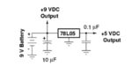
Finally, while possibly overkill - I'd like to see some decoupling of the VCO supply voltage for optimum stability/output power. Given you don't care about supply rejection/VCO noise in this application - for the VCO shown, dump the ferrite bead and the 10 ohm resistor, make the supply voltage a nice regulated 8.0V and add some generous decoupling right at the pins/pads of the VCO - something like a parallel group of 10p, 1n & 100n 0603 chip capacitors would keep any model of oscillator happy.
This site uses cookies to help personalise content, tailor your experience and to keep you logged in if you register.
By continuing to use this site, you are consenting to our use of cookies.
")