engr_joni_ee
Advanced Member level 3
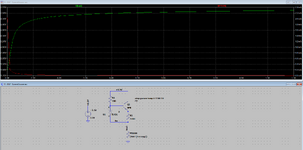
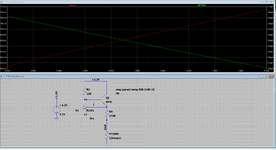
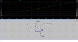
Hi, I need to change the value of PT1000 resistance from 900 Ohm to 1100 Ohm and probe the voltage across the PT1000
and also probe the current through it. I am not sure how to setup run man settings. Please guide me with the settings.
Thanks in advance.

and also probe the current through it. I am not sure how to setup run man settings. Please guide me with the settings.
Thanks in advance.