Continue to Site

Welcome to EDAboard.com

Welcome to our site! EDAboard.com is an international Electronics Discussion Forum focused on EDA software, circuits, schematics, books, theory, papers, asic, pld, 8051, DSP, Network, RF, Analog Design, PCB, Service Manuals... and a whole lot more! To participate you need to register. Registration is free. Click here to register now.

Need help about Inverter

Status
Not open for further replies.

aiubmehedi

Newbie level 4
Joined
May 11, 2012
Messages
6
Helped
0
Reputation
0
Reaction score
0
Trophy points
1,281
Activity points
1,319
1.jpg

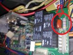
I have seen on many commercial ups uses like this in the circuit. can anyone explain why this film capacitor & resistor (Red circled) is used in output? what is the advantage of using this? i want use like this in my home 1000w inverter output. so, what should be the value of capacitor & resistor and how to connect with output?
 

i think it is used to avoid spikes ? (cannot be predict without seeing the circuit diagram)
 

Capacitor is connected to UPS output voltage and resistor to Neutral.
Expecting help from others...
 

Dear aiubmehedi
Hi
It is simple . it used to remove High frequency noises . because a film capacitor has a lower ESL and ESR instead of electrolytic .
Best Wishes
Goldsmith
 

It is probably used to filter out any noise or spike in the UPS output.

You can try with capacitor values of 0.1uF, 0.22uF and 1uF. The value itself shouldn't be too critical. You can use the 3 values mentioned and try. Observe the output on an oscilloscope to see if you can detect any spikes or noise and adjust the value of the capacitance to remove/minimize the spike/noise.

Hope this helps.
Tahmid.
 

Dear aiubmehedi
Hi
It is simple . it used to remove High frequency noises . because a film capacitor has a lower ESL and ESR instead of electrolytic .
Best Wishes
Goldsmith
Thanks GoldSmith
It is probably used to filter out any noise or spike in the UPS output.

You can try with capacitor values of 0.1uF, 0.22uF and 1uF. The value itself shouldn't be too critical. You can use the 3 values mentioned and try. Observe the output on an oscilloscope to see if you can detect any spikes or noise and adjust the value of the capacitance to remove/minimize the spike/noise.

Hope this helps.
Tahmid.
Thanks Tahmid. what should be the value of resistor?
 

The diagram shows a 4.7k resistor.

You can try with a 1k, 4.7k and 10k resistor and see the results.

However, it shouldn't be too critical.

Hope this helps.
Tahmid.
 

Status
Not open for further replies.

Similar threads

Part and Inventory Search

Welcome to EDABoard.com

Sponsor

Back
Top