jianhuachews
Member level 2
Hi guys.
Ok i have been googling and looking up in the forums for days but i still am very unsure about keypad interfacing. I want to design a 4x4 keypad decoder in FPGA using vhdl, and then display it on the 7 segment led of my nexys 2 spartan 3e board.
When pressed, ie: 5, on the keypad, the 7 segment should show a 5.
I understand that a 4x4 keypad has 4 inputs and 4 outputs (row and column) but how do i go about scanning which keys are actually detected? I've seen this term called like "de-bounce" but i totally has no idea what it really does. Also, how do i know which 2 pins of the keypad are for which push buttons?
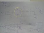
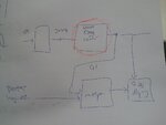
I'm really confused on what i should do. Do i need a block diagram to implement this so that it'll be easier for me to understand?
Last edited:

