Continue to Site

Welcome to EDAboard.com

Welcome to our site! EDAboard.com is an international Electronics Discussion Forum focused on EDA software, circuits, schematics, books, theory, papers, asic, pld, 8051, DSP, Network, RF, Analog Design, PCB, Service Manuals... and a whole lot more! To participate you need to register. Registration is free. Click here to register now.

[Need Advice] Low Noise Amplifier with source resistance 1 kohm

Status
Not open for further replies.

Aamir M

Newbie level 1
Joined
Jan 27, 2011
Messages
1
Helped
0
Reputation
0
Reaction score
0
Trophy points
1,281
Activity points
1,289
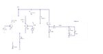
I am designing a low noise amplifier with 1 k source resistance with bandwidth 0-400 Hz. My amplifier goes into a transformer amplifier stage with effective impedance 0.5 ohm in series with 0.5 H, in parallel with 1.6 uF capacitor. The transistors have been chosen and biased accordingly for minimal noise output from the transistors.

(a) I used ac coupling capacitor of 24 mF. The gain is found to somewhat vary when the excitation frequency of the lock-in is varied.

(b) How would I calculate how much noise is added from the 100 kohm resistor and the 10 kohm in the emitter follower, and from the 3.3 kohm in the diff. amplifier.
 

Attachments

  • Amplifier with transformer.JPG
    Amplifier with transformer.JPG
    37.9 KB · Views: 122

Hello,

Just add a voltage source in series with the resistor, or a current source in parallel. For the voltge spectral noise you can use sqrt(4kTR) [V/rtHz]. When you use a 1V source (in AC simulation), and the effect at the output is 0.1V, then the voltage spectral noise from the resistor (sqrt(4kTR)) is attenuated with factor 10. When you do this for all resistors, then you know the resistor that introduces most noise. If you want to know the total noise, you need to add the effect of all resistors based on non-coherent addition.

So total spectral noise voltage is sqrt(V1^2 + V2^2....+ Vn^2).

The 10 kOhm resistor will add few noise as it looks into the emitter (has low impedance). The 100 kOhm resistor (R4) will add few noise when C2 has reactance < 3.3 kOhms. However for low frequency (where C2 has high impedance), the 100 kOhm resistor (R4) will add lots of noise, as it looks into the high input impedance of the emitter follower. Virtually all noise EMF will appear at the basis.

For high frequency, R4 and R2 are in parallel, so effect of R4 is negligible.

Of course the noise component in the base current of the emitter follower will create a separate noise voltage across R4 also.

As you are working at low frequency, you may check the noise specification of the resistors (if present). Noise production from resistors at low frequency can be far above the thermally generated noise. Same is valid for the noise components in the BJTs.

Note that the output impedance of this amplifier will be << 10kOhm as you look into the emitter.
 

    V

    Points: 2
    Helpful Answer Positive Rating
Status
Not open for further replies.

Part and Inventory Search

Welcome to EDABoard.com

Sponsor

Back
Top