Continue to Site

Welcome to EDAboard.com

Welcome to our site! EDAboard.com is an international Electronics Discussion Forum focused on EDA software, circuits, schematics, books, theory, papers, asic, pld, 8051, DSP, Network, RF, Analog Design, PCB, Service Manuals... and a whole lot more! To participate you need to register. Registration is free. Click here to register now.

Need a circuit to convert 0.6 Volts D.C. to 13 Volts D.C.

Status
Not open for further replies.

pmadithya

Member level 1
Joined
Aug 30, 2012
Messages
35
Helped
0
Reputation
0
Reaction score
0
Trophy points
1,286
Location
Bangalore,India
Activity points
1,530
Hi,

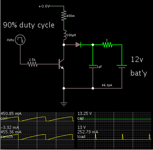
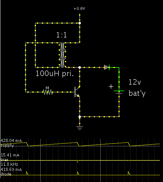
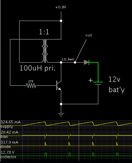
I have a Fuel cell Source rated at 0.6V,0.4A,33mW and i need to charge a 12V battery.
I need to help to boost D.C. voltage from 0.6V,0.4A,33mW to 13 V. Is there any circuit for it.
Or is there a two step process, maybe two boost converters back to back.
 

If your source is 0.6V at 0.4 A...

then the greatest charge you can give a battery at 13V...
is 18mA average (not counting losses).
If you're lucky you might get 0.2 A bursts at a 4% duty cycle. A lot of juice will be wasted.

0.6V will not turn on a transistor switch by itself, but you could turn it on from the 12V battery, theoretically.


The 1 ohm resistor is there to cause the capacitor to develop over 13 V momentarily, showing that the boost convert does deliver an output volt level which rises high enough to charge the battery.

Effort must be made to minimize any resistance in the power loop. The 0.4 ohm resistor represents some amount of impedance.
 

best is to use the 'joule thief' type of circuit. if you google, you will get lot of ideas.
also google 'energy harvesting circuit'.

It is like circuit of bradtherad, but it generates its own base signal using transformer saturation concept
 

Yes, the joule thief is certainly worth a try. I'm running a simulation.

I find that the 12V battery sends current into the 0.6V source. A diode is needed to prevent this. Then it will work.

Screenshot:


The transformer is easy to make. The primary and secondary each consist of a few windings of thin wire around a small ferrite core.

Notice that you still get brief current bursts at an occasional duty cycle.
 
Hi,

I'm developing an application called Hybrid Solar-Fuel cell off grid kit.

I'll be using a solar cell to power a Hydogen Fuel cell which is then used to charge a 12 V rechargeable battery.

The No Load Voltage of the solar cell is approximately 3 Volts. During solar-powered electrolysis, you can typically expect to generate approximately 1.7 Volts.

The fuel cell has a No-Load Voltage of about 1.7 Volts and an Operating Voltage of about 0.9 V having a current in the range of 100 to 300 mA.

So i need to boost 0.9 V,300mA to charge a 12V rechargeable battery.

Please do suggest me a suitable converter.
Please do suggest a suitable converter to get a appreciable voltage to charge a 12V rechargeable Battery.
And its a standalone device having no auxillary supply,so the only supply is 0.9 V, 0.3A(300mA)
 
Last edited:

Hi,

I'm developing an application called Hybrid Solar-Fuel cell off grid kit.

I'll be using a solar cell to power a Hydogen Fuel cell which is then used to charge a 12 V rechargeable battery.

The No Load Voltage of the solar cell is approximately 3 Volts. During solar-powered electrolysis, you can typically expect to generate approximately 1.7 Volts.

The fuel cell has a No-Load Voltage of about 1.7 Volts and an Operating Voltage of about 0.9 V having a current in the range of 100 to 300 mA.

So i need to boost 0.9 V,300mA to charge a 12V rechargeable battery.

Please do suggest me a suitable converter.
Please do suggest a suitable converter to get a appreciable voltage to charge a 12V rechargeable Battery.
And its a standalone device having no auxillary supply,so the only supply is 0.9 V, 0.3A(300mA)

The 'joule thief' step-up converter should work for you too. It is stand-alone.

Here's a theoretical screenshot:


The transistor has bias currents which surge to 20mA at one time and about -40mA other times. The transistor should be rated to withstand this.

A suitable wire gauge to carry 300mA is 28 AWG.

The battery may get an average of 20mA charging current if you're lucky.
 
There are some bright ideas here, but any circuit described offer a poor efficiency as all known active semiconductors need more than 1...2 V to operate.
On the other hand it is easy and requires no circuits to use several sources in series, to get either the needed 12 VDC, or at least 3...5 V to use a buffer circuit.
 

Hi,

Can you tell me which software u have simulated this circuit in.
I'm able to see a Simulation diagram. And what kind of diode should I use here.
 

Yes, the simulator is Falstad's. It is animated and interactive.

The link below will open his website, load my schematic, and run the simulation on your computer. (Click Allow to load the Java applet.)

https://tinyurl.com/axoaqol

You can alter values at will. Right-click a component and select Edit.

And what kind of diode should I use here.

I guess you mean transistor. NPN general purpose will do.

It does not appear to carry high watts, so a small signal type could do the job. It should be able to withstand high voltage. The reason is that if you disconnect the battery, the coil is likely to generate high voltage spikes.
 

Status
Not open for further replies.

Part and Inventory Search

Welcome to EDABoard.com

Sponsor

Back
Top