Continue to Site

Welcome to EDAboard.com

Welcome to our site! EDAboard.com is an international Electronics Discussion Forum focused on EDA software, circuits, schematics, books, theory, papers, asic, pld, 8051, DSP, Network, RF, Analog Design, PCB, Service Manuals... and a whole lot more! To participate you need to register. Registration is free. Click here to register now.

Need a circuit design for tuning the leading and trailing edge of a squre pulse

Status
Not open for further replies.

nigareipu

Newbie level 2
Joined
Jul 19, 2013
Messages
2
Helped
0
Reputation
0
Reaction score
0
Trophy points
1
Activity points
21
Hi,
I have a circuit for generating square pulses of different width. But I also need to add extra electronics to control the leading and trailing edge of that pulse. Can anyone suggest me circuit design to do that.
 

Hi, you could use monoflops or simple RC delay with a schmitt-trigger/comparator. Depending an the accuracy a digital solution with counter may also make sense.

Enjoy your design work!
 

You should talk a little bit about time scales. May be ps up to ms, circuits would be respectively different.
 

As FvM stated we need more info about the signal required. What is the maximum frequency, the minimum pulse width, and the rise and fall time variation needed.
 

You should talk a little bit about time scales. May be ps up to ms, circuits would be respectively different.

from a digital flip flop i have an output of 20us pulse having very sharp rise and fall time. But for next stage of this circuit i do need same pulse with almost 200ns rise time and 200-400ns fall time. To do so I added a RC integrator. In this case, within the rise and fall time the signal rises and falls exponentially. but I need a circuit that can make the rise and fall linearly within the time limit.

- - - Updated - - -

I have a varying pulse of width 2us to 30us with very sharp rise and fall time. but i need to create same pulse with 200ns rise time and 200-400ns fall time where within these time the signal should rise and fall linearly.
 

I have a varying pulse of width 2us to 30us with very sharp rise and fall time. but i need to create same pulse with 200ns rise time and 200-400ns fall time where within these time the signal should rise and fall linearly.
You'll need to refer to active pulse shaping circuits with current sources, diodes, transistors or operational amplifiers. The intended voltage and timing accuracy is an important design parameter.

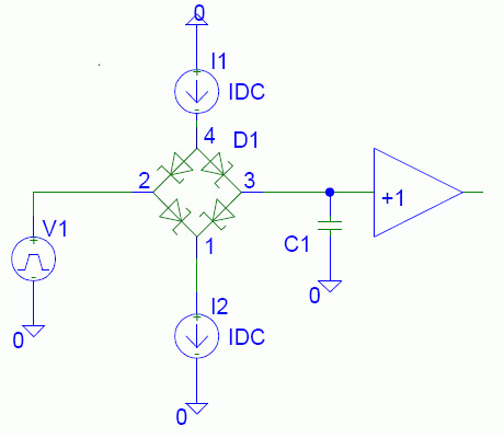
A principle circuit example of a slew rate limiter:

2976300100_1374565437.gif
 

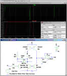
Below is a circuit to give a linear independently controlled rise and fall time. It consists of two switched complementary current-mirrors driving a capacitor. R4 controls the rise-time and R2 controls the fall time. The values shown give a nominal rise-time of 200ns and a fall-time of 300ns. You can make them adjustable by adding a pot in series with R2 and R4 (reducing the value of R2 and R4 accordingly).

C3 minimizes distortion due to crossover effects.

U1 is a high speed, rail-rail op amp to buffer the output.

Controlled Rise-Fall Time Ckt.gif
 
Last edited:
I saw an article by the late Bob Pease a few years ago about adjustable slew rate amplifier. I managed to find it on Google again. Typical Bob style design. Enjoy!
**broken link removed**
 

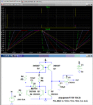
For those interested, the adjustable rise and fall time of my circuit is shown below by stepping the two resistor values:

Controlled Rise-Fall Time Ckt.gif

Edit: Note that the NPN transistors are high speed switching types. Substitution of general purpose transistors like the 2N2222 (particularly for Q6) may require some tweaking of the circuit values to get the desired response.
 
Last edited:

Status
Not open for further replies.

Similar threads

Part and Inventory Search

Welcome to EDABoard.com

Sponsor

Back
Top