boylesg
Advanced Member level 4
- Joined
- Jul 15, 2012
- Messages
- 1,023
- Helped
- 5
- Reputation
- 10
- Reaction score
- 6
- Trophy points
- 1,318
- Location
- Epping, Victoria, Australia
- Activity points
- 11,697
I have finally got my Gate Drive Transformer driver working after I ironed out a really stupid mistake I made, i.e. wired the NPN emitter to the PNP collector (rather than its emitter). I was in 'half bridge' mode when I soldered it.
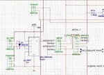
But this is what I have:

Basically I am going to run dual tesla coils so there are twin interrupter and twin aerial inputs on another board.
The headers in the schematic above are not actually headers but rather those white (usually) plastic connectors you see on CRT tv circuit boards. I don't know the correct name for them. I have soldered the POT leads and the 2-pole switch leads to the end of the wires in order to make it easy for myself to mount the circuit in a box later.
The capacitor header is one of those arduino connectors so that I can easily switch timing capacitors and get the right frequency.
Basically I have allowed myself the options of being able to tune the Tesla coils either from the noise they generate through an aerial (and Schmidt trigger inverters to stabilise the signal) or from a fixed square wave from an astable 555 with an interchangeable timing capacitor. The 2-pole 2 position switch allows the aerial input of the AND gates below to be switched between the two.
The interrupter signals from the other board go straight into the AND gates from the other boards to give the same functionality as the enable pin on UCC27425.
And then I have the above connected to two of these circuits corresponding to each tesla coil.

I decided to put an opamp buffer between the AND gate outputs and the darlington bases to make sure the voltage on the bases is as close to rail as possible. The logic gates can only manage perhaps a 1uA output at rail voltage.....thankyou Audioguru.
So I can successfully drive a LED from my circuit in both directions using fixed voltage inputs in liue of the inputs form the other board.
So I guess the next step is to hook it up properly and have a look at what I get with my scope.
But this is what I have:

Basically I am going to run dual tesla coils so there are twin interrupter and twin aerial inputs on another board.
The headers in the schematic above are not actually headers but rather those white (usually) plastic connectors you see on CRT tv circuit boards. I don't know the correct name for them. I have soldered the POT leads and the 2-pole switch leads to the end of the wires in order to make it easy for myself to mount the circuit in a box later.
The capacitor header is one of those arduino connectors so that I can easily switch timing capacitors and get the right frequency.
Basically I have allowed myself the options of being able to tune the Tesla coils either from the noise they generate through an aerial (and Schmidt trigger inverters to stabilise the signal) or from a fixed square wave from an astable 555 with an interchangeable timing capacitor. The 2-pole 2 position switch allows the aerial input of the AND gates below to be switched between the two.
The interrupter signals from the other board go straight into the AND gates from the other boards to give the same functionality as the enable pin on UCC27425.
And then I have the above connected to two of these circuits corresponding to each tesla coil.

I decided to put an opamp buffer between the AND gate outputs and the darlington bases to make sure the voltage on the bases is as close to rail as possible. The logic gates can only manage perhaps a 1uA output at rail voltage.....thankyou Audioguru.
So I can successfully drive a LED from my circuit in both directions using fixed voltage inputs in liue of the inputs form the other board.
So I guess the next step is to hook it up properly and have a look at what I get with my scope.