Continue to Site

Welcome to EDAboard.com

Welcome to our site! EDAboard.com is an international Electronics Discussion Forum focused on EDA software, circuits, schematics, books, theory, papers, asic, pld, 8051, DSP, Network, RF, Analog Design, PCB, Service Manuals... and a whole lot more! To participate you need to register. Registration is free. Click here to register now.

My quarterwave coupler is not working after ADS simulation

jadnounyah

Junior Member level 3
Joined
Aug 21, 2022
Messages
30
Helped
0
Reputation
0
Reaction score
0
Trophy points
6
Activity points
297
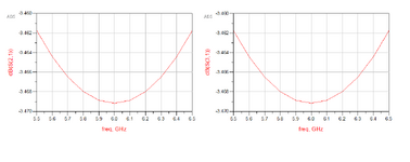
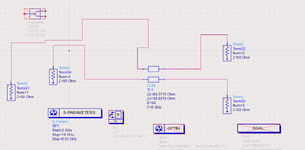
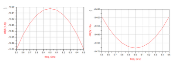
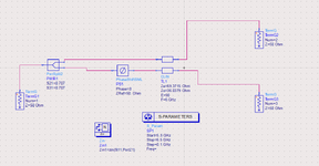
So for a coupling coefficient of 10 dB (essentially -10dB), I calculated the odd and even mode impedances of the ideal coupler to be as shown in the figure below for Zo and Ze respectively. Ideally running an Sparameter simulation is supposed to give me an S31 value of the -10 dB since it refers to the coupling coefficient but it gives me some other way off value which is surprising cause I don't know what the issue could be. Any help will be greatly appreciated. Find attached the schematic setup for the coupler analysis and the results upon performing simulations at 6 GHz.
 

Attachments

  • 11111111coupler issue data display.png
    11111111coupler issue data display.png
    16.4 KB · Views: 72
  • 11111111coupler issue schematic.png
    11111111coupler issue schematic.png
    62.9 KB · Views: 70
Port-4 is Coupled Port, Port-3 is Isolated Port in your case.
Interchange the port numbers like me.
1706815127195.png

1706815109423.png
 
Solution
I am still puzzled why both through port and isolated port are at -3dB in the initial post. Does the plot show the correct dataset?
 
Thanks alot now that works, so I wanted to perform odd and even mode analysis on the same coupler and the setup is shown in the figure attached, the s31 value changed to -3.5 dB there and i don't know if it's the schematic setup again, since here I can't actually place a 4th port. If I could insight into why the results are so, I would be grateful. I think maybe it's because of the 3dB power split at the input but I'm not too sure about that thanks.
--- Updated ---

yes those were the results obtained after the simulation, pretty surprising
--- Updated ---

I am still puzzled why both through port and isolated port are at -3dB in the initial post. Does the plot show the correct dataset?
Yes it is, I also don't have any idea, prolly it's attributed to the wrong port assignments?
 

Attachments

  • 122222_coupler work issue data display.png
    122222_coupler work issue data display.png
    17.8 KB · Views: 46
  • 122222_coupler work issue schematic.png
    122222_coupler work issue schematic.png
    41.1 KB · Views: 53
so I wanted to perform odd and even mode analysis on the same coupler
For odd mode, you can connect a port with explicit reference node (Term, not TermG) between the two inputs/outputs.
For even mode, you can connect the inputs/outputs in parallel.

Another possibility is the Balun4Port element in palette System-Passive, this has two terminals for the device (mixed mode) and one terminal each for differential mode and common mode. I use that element a lot for testing mode conversion.
I understand your point and thank you for the feedback. But with my circuit, what could be causing the "error" with the coupling coefficient graph, is it because I'm "omitting" one port ? Or my circuit just won't work cause ideally I'm supposed to use this setup in the schematic to determine the even odd mode analysis of the coupler.
 
But with my circuit, what could be causing the "error" with the coupling coefficient graph
I really think you plotted the wrong dataset (results from another other simulation).

If I reproduce your exact case, including your port numbers, I get meaningful data.

clin.png
 
Interestingly, the classical convention for Directional Coupler does not fit into this simulation.

Input: Port-1
Output: Port-2
Coupled: Port-3
Isolated: Port-4


But the simulation results of Volker show us this convention is not "unique" for all cases.
OR, s-matrix of Coupled Lines in ADS is different than this convention.
 
@BigBoss I think your picture is only a schematic one. In physical implementation of transmission line couplers, the diagonal port is isolated.

My results are identical to yours in #2, I just wanted to show @jadnounyah that his exact schematic does not give the results that he showed.
 
I really think you plotted the wrong dataset (results from another other simulation).

If I reproduce your exact case, including your port numbers, I get meaningful data.

View attachment 188458
I'm pretty sure it was the data display I brought on here, I don't know what was wrong too. I have fixed that but with respect to the new circuit I have added(with the divider and shifter) above in one of the comments . How am I not getting the coupling coefficient graph showing a -10 dB value. Thanks alot.
--- Updated ---

Interestingly, the classical convention for Directional Coupler does not fit into this simulation.

Input: Port-1
Output: Port-2
Coupled: Port-3
Isolated: Port-4


But the simulation results of Volker show us this convention is not "unique" for all cases.
OR, s-matrix of Coupled Lines in ADS is different than this convention.
Honestly to some extent I actually thought the port numbers didn't matter much until my attention was drawn to it so maybe it's his settings in the ADS allowing him to do that. Maybe jut maybe.
 
I described in #5 the proper way to do arbitrary even/odd mode excitation and termination (!) with the Balun4Port, instead of your divider/phase shifter approach.

The port numbers in ADS don't matter, as long as you interpret things correctly for the actual port configuration. Bigboss was showing a symbolic coupler that where the isolated port is on the other side, that is different from physical realization of a line coupler.
Yhyh I understand your method but from the attachment I have included, see I am supposed to follow specific steps to get the even/ odd mode analysis and that is why I am kind of trying to find the issue with it. I am not denying the effectiveness of your method.
1708093507166.png
 
@jadnounyah Yes, with that configuration you get the -3dB results from your initial post. You then do NOT get the -10dB coupling, of course, because you drive both lines simultaneously.

Your text says you need to measure the input impedance. You get this in ADS with the data display equation Zin=stoz(S(1,1)) shown below, and find the common mode and differential mode values as input impedance. I think this is what your teacher wants you to see.

config.png


0 degree phase offset for common mode:
phase0.png


180 degree phase offset for differential mode:

phase180.png
 
@jadnounyah Yes, with that configuration you get the -3dB results from your initial post. You then do NOT get the -10dB coupling, of course, because you drive both lines simultaneously.

Your text says you need to measure the input impedance. You get this in ADS with the data display equation Zin=stoz(S(1,1)) shown below, and find the common mode and differential mode values as input impedance. I think this is what your teacher wants you to see.

View attachment 188677

0 degree phase offset for common mode:
View attachment 188678

180 degree phase offset for differential mode:

View attachment 188679
Oh alright then, I did obtain the answers then, I obtained such results as you did as well. Thanks alot. I actually thought since I wasn't getting the -10 dB coupling coefficient I was wrong.
 

LaTeX Commands Quick-Menu:

Part and Inventory Search

Welcome to EDABoard.com

Sponsor

Back
Top