jengsyber
Newbie level 5

- Joined
- Jan 27, 2009
- Messages
- 8
- Helped
- 0
- Reputation
- 0
- Reaction score
- 0
- Trophy points
- 1,281
- Activity points
- 1,343
Follow along with the video below to see how to install our site as a web app on your home screen.
Note: This feature may not be available in some browsers.


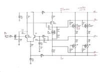
I was puzzled too, that's why I asked it's purpose. The supply voltage seems way too high for audio work but the input and feedback circuits suggest it's for low frequency use. I thought it might be part of a motor drive circuit but I would expect it to have some output protection if it was. Maybe it's 'theoretical' but never simulated or built and the design flaws haven't been exposed yet.
Brian.


It sounds like you are making a heater instead of making a sinewave inverter.
If you learn how to design or copy a linear Mosfet power amplifier then you will know that it heats almost the same amount as the load. A waste of power.

It sounds like you are making a heater instead of making a sinewave inverter.
If you learn how to design or copy a linear Mosfet power amplifier then you will know that it heats almost the same amount as the load. A waste of power.
A real sinewave inverter uses Pulse-Width-Modulation (PWM) to make a stepped sinewave then its output Mosfets switch completely on and off at a high frequency. Since when they are switched on and the voltage across them is very low then they do not get hot and when they are switched off and do not conduct then they also do not get hot. The high frequency steps are easily filtered out.


You can make a PWM sinewave with as many bits as you want. But 8 bits at 400Hz is a frequency that class-D PWM audio amplifiers work at.


No. "Bits" don't come into it. They can run at much lower frequencies than that.A class-D amplifier is expensive because its parts must make maybe 8 bits at 10kHz. Then the clock is at the very high frequency of 2.56MHz if my calculation is correct.
