Continue to Site

Welcome to EDAboard.com

Welcome to our site! EDAboard.com is an international Electronics Discussion Forum focused on EDA software, circuits, schematics, books, theory, papers, asic, pld, 8051, DSP, Network, RF, Analog Design, PCB, Service Manuals... and a whole lot more! To participate you need to register. Registration is free. Click here to register now.

My Intelligent Curve Tracer

Status
Not open for further replies.

locky_z

Newbie level 2
Joined
Feb 1, 2012
Messages
2
Helped
0
Reputation
0
Reaction score
0
Trophy points
1,281
Activity points
1,318
It use USB or RS232 interface communication with PC and show the semiconductor curve in PC screen.

It can measure BJT's Ic->Hfe curve
1.png

Can measure Vce-Ic curve
2.png

measure some semiconductor transmission curve,such as Vbe-Ic / Vgs-Id
3.png


also FET’s Vds-Id curve measure,Even can study Vgs & Rds relationship
4.png

Upper is six IRF630 Vds-Id curves,their Vgs is 5V 6V 7V 8V 9V 10V.
The Vds-Id curve only show Vds=0~1V range,so you can use system’s calculate function get the slope value,
The window in the central show six curve’s slope, Measurement unit is V/mA, multiplicate 1000 is Rds,
So under Vgs=10V,Rds is 0.000334649870637804*1000=0.334ohm

Some diode V->I curve
5.png

fllower is TL431 in all current range V-I curve
6.png

if you plug TL431 into socket B and E,and change the measure condition,you can see less current VI curve. The following figure , Y-axis is only 0~0.38mA
7.png

the Intelligent Curve Tracer is more powerful,It can measure 3 terminal voltage regulator’s Vi-Vo / Io->Vo Curve
8.png
 

Intelligent Curve Tracer Principle

Before talking about my Intelligent Curve Tracer principle,I talk about the general measure curve principle by MCU first.
The general measure diagram as in Figure
P1.png

Mcu control Channel B/C DAC and OCL power amplifier to driving the DTU, And measure four voltage(VBH/VB/VC/VCH) by ADC, and then calculate the Ib/Ic/Vce/Vbe and then draw the Vbe-Ic/Vce-Ic/Ic-Hfe curve.

Because of the need for the measure of P and N type semiconductor,so all the voltage are bipolar.
But considering the component selection, Most of the DAC and ADC can only output or measure unipolar voltage,bipolar ADC price will be very expensive.
Considering the cost of it, it uses unipolar ADC/DAC a lot cheaper, choice scope is much extensive.

So if we use unipolar ADC/DAC to design the curve tracer,we need some additional circuit:
1.four amplifier,It’s gain is –1, purposes to change negative voltage to positive voltage,so that the ADC can handle.
2.two amplifier to offset DAC to bipolar voltage;
3.Need biporlar power supply, but the DTU’s vce voltage range is only half of the total supply voltage;
4.Need 8 channle ADC to measure vbh1/vbh2/vb1/vb2/vch1/vch2/vc1/vc2;

My intelligent Curve Tracer in the above principle to make an improved, Using the" three voltage amplifier to drive DTU, the DTU emitter isn’t connect to ground, but from a voltage source,.
P2.png

The emitter voltage source(Channel E Power Amp) is very critical, completely solve the shortcomings of the above,.
for example
Measure NPN BJT,We set Channel E Power Amp to output 2.5V, and set Channel B/C Channel power amplifier to output more then 2.5V,such as B channel is 5V, C channel is 20V,so the NPN can work. We measure the Ve/Vbh/Vb/Vc/Vch then calculate the Vbe/Vce/Ib/Ic/Hfe and draw the curve.
If measure PNP BJT,We set Channel E to output 40V, and set Channel B/C Channle to output less then 40V,so PNP can work. We also measure the Ve/Vbh/Vb/Vc/Vch then calculate the Vbe/Vce/Ib/Ic/Hfe and draw the curve.
If measure N type J-FET,We connect JFET’s source to E, grid to B, Drain to C. and set E channel output 10V,and set B Channel is from 2.5V to 10V, and set C Channel output from 10 to 40V. This means that the JFET’s Vgs is –7.5 to 0V,and Vds is from 0 to 30V. This is the JFET normal operating voltage range.
You look back above example, All the measure voltage are unbipolar,so DAC and ADC are just use a unipolar model device.
And the solution only need a 40V unbipolar power supply, and the DTU Vce range can be from 0 to 40V.

Actual circuit
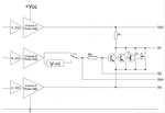
1.three channel power amplifiers
P3.png

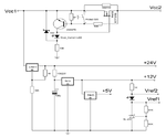
2.power supply and protect circuit
P4.png

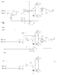
3.MCU & ADC & DAC & Control circuit
P5.png


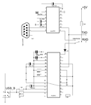
4.USB and RS232 interface circuits
P6.png


P7.png
 

Hi,

Are you still working on this project?

This could be a good start for the project that I have myself in mind.

But to suit the needs that I have and my goals, there would be a need for some changes.

Plus the software side would have to be portable, because I would not use windows.

One of my needs is to compare for matching power transistors, so the tests should be able to go further up in power levels and voltages as well, so those could be more fully tested for real use.

I have no need to test anything else beyond bjts, which would keep such a device more simple, and the software as well.

If you are still active on the project, perhaps we can exchange on it.

Thanks
 

Status
Not open for further replies.

Similar threads

Part and Inventory Search

Welcome to EDABoard.com

Sponsor

Back
Top