Continue to Site

Welcome to EDAboard.com

Welcome to our site! EDAboard.com is an international Electronics Discussion Forum focused on EDA software, circuits, schematics, books, theory, papers, asic, pld, 8051, DSP, Network, RF, Analog Design, PCB, Service Manuals... and a whole lot more! To participate you need to register. Registration is free. Click here to register now.

My First receiver:Mixer & IF

Status
Not open for further replies.

froten

Member level 3
Joined
Jun 17, 2006
Messages
56
Helped
1
Reputation
2
Reaction score
1
Trophy points
1,288
Activity points
1,798
Hello all,

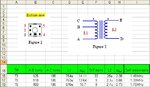
I have starting building the proto type of my receiver circuit. I started by the mixer+IF stage. Attached is the schematic, PCB (before modifications) and transformers details. The transformers are rewond of some old toko coils I have on hand.

The resulting circuis caused me many nightmares, it is oscillating, noisy and refuses to work for me.

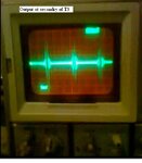
Attached also is a picture of the output at detector D1. When I disconnect C13 & C19 oscillation stops, also if I lower the gain by adding un-bypassed resistor at the emitters the oscillation stops too.

Checked in many text books for solutions and techniques, found nuetralization techniques but none of them worked. For example, I tried to connecte a capacitors (ranging from 2pf to 47pf) from the pin 1 on T6, T5 & T3 to the base but still unstable, tried to use pin 3 for the same thing but still the same.

When I disconnect the stage of Q3, the oscillation stops.

What is going wrong with my design? This simple circuit I was thinking I will build during the week end, and it is now the fourth week without any success.

Any help is appreciated.
 

Attachments

  • IF stage PCB.pdf
    45.5 KB · Views: 126
  • IF stage.pdf
    59.6 KB · Views: 143
  • Output at secandry of T3.JPG
    Output at secandry of T3.JPG
    23.5 KB · Views: 171
  • Transformers details.JPG
    Transformers details.JPG
    43.1 KB · Views: 182

What is value of R21? I assume it is also 1K.

Have you aligned all the 455 kHz tanks?

Put some shunt load resistance across collector tanks in parallel with 220 pf caps. 3k to 20k range. This will decrease Q, reducing selectivity, but make stage more stable.

LO drive should be set to increase mixer current by about 15-25% above no LO idle bias. Measure voltage across R7 to determine delta current.
 
Last edited:

R21 is 470 Ohm. tried to allign the tank circuits when C13 & C19 are disconnected, I know reinstalling these caps will effect The tank circuits tuning, but this is the only way I could use because the circuit is unstable.

1) Is said before, when Q3 stage is removed the circuit is stable and can be alligned. does this mean that the unstability is caused by Q3?
2) IS the input impedance of the transistors not enough to load the tank circuits? do I need to decreas the turns ratio of the tranformers?

1) maybe but not necessarily. If you have a plastic handle tuning tool with a metal blade at end you can short E-B of each stage to shut down the stage.
2) not the same as a dead weight resistor. An unstable stage can present a negative input resistance. When negative resistance outweights positive resistance the stage oscillates.

Negative resistance from one stage can kick back lighter load to previous stage causing it to be unstable, which cause next previous stage to be unstable. Cascade effect.
 
Last edited:

I'll try tommorow to connect a resistor.

But:

1) I would like to know, what is causing the oscillation, Is it the capacitance between collector and base Ccb? The collector is 180deg out of phase with the base, so how it can cause unstability?

2) Is it correct to consider the Ccb & Cbe as capacitive voltage divider for the collector voltage to the base?

3) in point 2, is it voltage divider or current divider?
 

Your grounding system is strung out and looping around. I particular don't like that the return of last stage emitter bypass goes back around top toward mixer end and back along bottom where it get tapped into by earlier stage.

Remove the last ground jumper wire from C19 and ground C19 to T5 shield tab. Same with jumper left of C13. Ground C13 to T6 shield ground tab.

Also put some bypass caps along B+ runner running along the top to transformer shields.

Suggestion for future PCB's. Use double sided copper board. Layout component side like a surface mount board, even leaded parts attached on surface pads only. If you are making your own board, tape over bottom to protect it from etching. Now any needed grounds can go straight down to ground plane on opposite side of PCB. Little 1.25 mm diameter eyelets are great to use for through holes to ground plane connection but just a wire will do.
 

Attachments

  • Leaded parts surface mount PCB.pdf
    593.1 KB · Views: 118
Last edited:
  • Like
Reactions: froten

    froten

    Points: 2
    Helpful Answer Positive Rating
Regarding R1, R8 and R15, is the current connection good or it is better to connect directly to VCC?
 

This receiver is a poor design.

If you are intending it for use up at 27MHz then you will have to fit a very steep filter to get adequate image rejection.

Also there is no AGC.

Also, the choice of mixer is a poor one.

The channel selectivity at the IF will be poor.

I assume the PCB has a continuous top layer of ground. I haven't looked closely at the PCB layout because this receiver design is a waste of time.
Forget about curing the instability. You need to start again. (unless you are going to use this receiver mixer/IF for short range comms at a reasonably fixed distance)

Why not buy a book with some proven DIY SW Rx circuits in it and build one of those? Do you wish to receive AM or SSB/CW or both?

What frequency range are you going to use it over?
 
Last edited:

G0HZU, can you please suggest any sites, links or books.

I'm trying to receive AM signals, and doing this project to get some expirince on RF design and construction.
 

The IF stages have a lot of gain, and even is low frequency is possible to oscillate, most probably due to layout feedback.
Using a capacitive divider in front of each IF stage, minimize the possibility of feedback.
L and C in the picture attached resonates on 455kHz.
 

Thanks vfone for your help. I 'll try out this circuit if I couldn't get mine to work.

In general, and as a rule of thump, how much gain should I get from each stage in the IF amp. I have seen some articles where some pepole limit the gain to 15db to 25db, is this applicable here? in this case, to get 80db, I'll need 3 or 4 stages for that.
 

The revised circuit still has no AGC so it will be stuck at high gain.
If you really want to make a basic SW AM receiver then you will need AGC.

If you want to make it with discrete transistors then can you get hold of JFET transistors? eg J310 or 2N3819.

You can arrange these in cascode and get AGC by varying the gate bias on the top FET. Or you can use a DG MOSFET (classic = 40673) but these cost more and can be harder to find.

With a cascode FET stage you can get high gain (>20dB) and also lots of AGC range and fairly good linearity over the AGC range. You could use the negative DC voltage from the AM detector to generate the AGC voltage via a simple DC amplifier and AGC RC time constant.

If you are not too worried about strong signal handling then you could do the first mixer as a cascode stage as well although I would favour a basic diode ring mixer.
Can you get hold of a ceramic filter for 455kHz? eg 6kHz bandwidth for AM?

Are you going to listen to AM broadcasts or use it for local telemetry?
 

The reason I'm dealing with AGC is that because I need to ensure stability at the highest gain, then when the circuit is stable, I'll add the AGC circuit, that is why the PCB contained the AGC parts places byt not connected.

Again, as a simple rule, what is the usual gain of each stage that I should get? too much will cause unstability, too litle is a waste of resources?

If we say the stage has to make 25db (18 times) gain, then considering the turns ratio (which is 20), then the gain of the transistor should be about 18x20=360.
 

There isn't enough info in your circuit to allow someone to work out the gain but it will be dependent on the transistor bias current and the impedance seen at the collector. I would expect you could get at least 25dB gain per stage.

However, you need to ask yourself why you are attempting to build an AM receiver design that will perform worse than just about every cheap pocket AM receiver produced since the 1960s.

Also, if you are going to get AGC by varying the base voltage/current to each stage then the linearity will suffer badly in the presence of large signals that lie close to your tuned frequency. The first mixer stage will become laughably poor (with AGC applied) if you used this receiver for the crowded lower SW bands during night time reception.

However, if you insist of getting it to work as intended then I would suggest you throw away the PCB and build it again on a sheet of bare copper PCB in 'dead bug' style. Make sure the transformers are well screened and it will probably work without going unstable.

Can you measure how much gain each (seperate) stage has by using an oscilloscope?
 

I fully agree with the previous posters but if you already have the circuit built, there is a "dirty" trick you could try: reverse the connections on the secondary of ONE of the IF transformers. It will not improve performance above what is achievable when the circuit is stable, in fact if it reverses the feedback polarity you will turn the positive feedback causing oscillation into negative feedback which reduces gain. It may be enough to get you started though.

Brian.
 

This receiver utilizes tuned amplifiers which is a basic building block, therefore I must get used to it, including stabilization and performance evaluation. Tuned amplifiers are used everywhere, so I really need to understand how to use it and stabilize it. All techniques I read on tuned amp stabilization didn't work with me, so I need to know why. Techniques like neutralization (connecting cap from either ends of tank circuit to base), adding resistor in collector or base, emitter degeneration didn't work, this is a big disappointing.

From the discussion so far, I realized a big problem with PCB layout which I’m working on again.

I appreciate your help and time reading and replying to my post, but I would like to get alternative suggestions or links to a better designs which for sure I'll try when I’m done with simple receiver.
 

any comments about the IF transformers? The coils were rewond on toko coils I had since long time without any datasheet. The contruction was based on the information provided on this web page:

if amplifier transformers

The following link was my start point in my receiver project:
am radio receivers
 
Last edited:

transformer details attached, including inductance, DC resistance and self reasonace frequency. The turns ratio is 20 for T6 & T5.
 

Attachments

  • Transformers details.JPG
    Transformers details.JPG
    43.1 KB · Views: 161

Did you do the recommended grounding changes?
 

Status
Not open for further replies.

Part and Inventory Search

Welcome to EDABoard.com

Sponsor

Back
Top