Continue to Site

Welcome to EDAboard.com

Welcome to our site! EDAboard.com is an international Electronics Discussion Forum focused on EDA software, circuits, schematics, books, theory, papers, asic, pld, 8051, DSP, Network, RF, Analog Design, PCB, Service Manuals... and a whole lot more! To participate you need to register. Registration is free. Click here to register now.

My first program in Proteus for PIC18F452

Status
Not open for further replies.

Maheen_Mazhar

Newbie level 6
Joined
Jan 27, 2011
Messages
14
Helped
0
Reputation
0
Reaction score
0
Trophy points
1,281
Activity points
1,394
Hi
I have just started learning PIC18 assembly language programming. I tried a simple code in MPLAB and it was successfully compiled and executed. By observing the values at the register it was confirmed.
But when I try to run the same code on Proteus, I get errors.

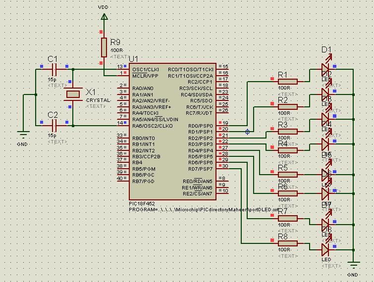
The program is made to turn LEDs 'ON' one by one, connected at PORTD.
At the end all 8 LEDs should be lit.

The code is:

PORTD EQU 0xF83
TRISD EQU 0xF95
ORG 0h
CLRF TRISD ;make PORTD an output port
BSF PORTD,0 ;bit set turns on RD0
NOP ;delay before next one
BSF PORTD,1 ;turn on RD1
NOP
BSF PORTD,2
NOP
BSF PORTD,3
NOP
BSF PORTD,4
NOP
BSF PORTD,5
NOP
BSF PORTD,6
NOP
BSF PORTD,7
NOP
END

In Proteus, when I click BUILDALL the following errors are encountered:

Error: Illegal opcode (TRISD)
Warning: found label after column 1 (CLRF)
Error: Illegal opcode (PORTD)
Warning: found label after column 1 (BSF)
 

Hi,

Which version of Proteus you use ? It's not a compiler nor assembler for PIC.
You have to generate *.cof or *.hex file using MPLAB then assign it as "program file" in proteus.

Thank you,
 

Try to import .hex file directly to Proteus. When you assemble your code in MPLAB, it generates the .hex file. Also, try to follow the format (codding style) suggested in template files located at C:\Program Files\Microchip\MPASM Suite\Template\Code or wherever they are located. As far as I know, MPLAB requires that only labels can occupy the beginning of a line, and any word which is placed to the beginning of a line (column 1) is considered as a label. Use tabs before writing the opcodes. I have no idea about Proteus (I don't use it) but it seems, it enforces the same rules.
 

What you need to do is double click the PIC18F452 in proteus it will open a window/dialogue box by the name of "Edit Component". Once it is open go to program file, and browse to the folder where you generated .cof and .hex file through MPLAB. Click on .cof ile, click open, press ok.
Now run the simulation it will work this time.
 

Thank you for your support.
But when I followed the your suggestion, after running my simulation, I got no output displayed at LEDs.
And these messages appeared in simulation log:
(PIC18 )PC=0x0A7C. Processor has been reset by watchdog timer expiring at time 2.304000
And this message repeated several times.

Plz tell me next step!

---------- Post added at 10:13 ---------- Previous post was at 10:11 ----------

I am using Proteus7.5
I tried to work with hex but could'nt succeed!

Any more suggestions?

---------- Post added at 10:21 ---------- Previous post was at 10:13 ----------

1. Yes I implemented the code for same PIC version that is PIC18F452
2. WHat i know the language is case sensitive, well still I'll try to do that.
3. I have done this, when I click PLAY
I got following message in simulation log:
(PIC18 )PC=0x0A7C. Processor has been reset by watchdog timer expiring at time 2.304000
And this message repeated several times.

Still, no success /\
 

Thank you for your support.
But when I followed the your suggestion, after running my simulation, I got no output displayed at LEDs.
And these messages appeared in simulation log:
(PIC18 )PC=0x0A7C. Processor has been reset by watchdog timer expiring at time 2.304000
And this message repeated several times.

Plz tell me next step!

---------- Post added at 10:13 ---------- Previous post was at 10:11 ----------

I am using Proteus7.5
I tried to work with hex but could'nt succeed!

Any more suggestions?

Now in the MPLAB open you project & in the tool bar there is a option configure click & go to configuration bit setting ther you need to disable the watch dogtimer & select your crystal frequency and press ok & then compile your code, build it, then add the hex to the processor property in protus isis it will work.
 

    V

    Points: 2
    Helpful Answer Positive Rating
I disabled watchdog timer, but how to set crystal frequency there?
 

You don't have to specify PIC Frequency in .asm file, just set the required crystal mode (LP, XT, HS) in configuration bits.
This is one of the ways configurations bits could be set in the assembly:
__config (_INTRC_OSC_NOCLKOUT & _WDT_OFF & _PWRTE_OFF & _MCLRE_OFF & _CP_OFF & _IESO_OFF & _FCMEN_OFF)
the other is
__config 0x3939
these bit are mcu specific, so you must read the data sheet of the mcu (in your case 18F452) to set the config bit, the section is called special features of the cpu.
 
Last edited:

I disabled watchdog timer, but how to set crystal frequency there?

watchdog timer reset uC when no code to process.
If your code is same in your post#1 ; uC has reached to end of code. You have to use a non-end loop to test the program.
You can clear portD at end then start over again from turning-on first-bit.

You may set uC clock-speed in "Edit properties" window by right-click on PIC in proteus.

Hope this helps you,
 

    V

    Points: 2
    Helpful Answer Positive Rating
I disabled watchdog timer, but how to set crystal frequency there?

As per the choice of crystal(frequency), select the crystal mode at configure in mplab.
 

    V

    Points: 2
    Helpful Answer Positive Rating
I disabled watchdog timer, but how to set crystal frequency there?

Have you got things working ? - it all sounds very confusing.

If you get that code working all it will do is turn on all the LEDS at one time , unless you slowly Single step through the code - your idea of using a delay is valid but the NOP will only take a few micro seconds, you need a delay of at least 250 milli seconds to see anything in real time.

It you are still stuck post your complete assembler code and the .dsn file you have created.
 

I have changed my code, the new one is OK in MPLAB, as it is successfully build and running, but I am unable to learn using PROTEUS simulator.

my code is now:
LIST P=PIC18F452
#include P18F452.INC
PORTD EQU 0xF83
TRISD EQU 0xF95
MYREG EQU 0x50
ORG 0
CLRF TRISD
BACK BSF PORTD,0
CALL DELAY
BSF PORTD,1
CALL DELAY
BSF PORTD,2
CALL DELAY
BSF PORTD,3
CALL DELAY
BSF PORTD,4
CALL DELAY
BSF PORTD,5
CALL DELAY
BSF PORTD,6
CALL DELAY
BSF PORTD,7
CALL DELAY
GOTO BACK
ORG 0X300
DELAY MOVLW 0X19
MOVWF MYREG
AGAIN NOP
DECF MYREG, F
BNZ AGAIN
RETURN
END

and my schematic is


I have disable WDT and set oscillator type XT.
I have made all these changes but problem persists
 
Last edited:

Hi,

Thats good that you have improved your code.

Attched is some similar code, but it is more complete.
It uses the Template file for the 452 found in the MPlab / Templates folder.

It may all seem a lot of code before you get to the Main section, but just concentrate on the main section for now.
The important thing of the template is the CONFIG statement which sets all those system paramenters - the one you are interested in is the OSC which is set to XT which is for crystals up to 4 meg.

On the design, you will see it is not neccessary to show the crystal, this is set by Editing the 452 in the design to show the crystal speed and where the .hex fle is located.

Also the pullup resistor on Mclre should be 10K, the resistors to the leds should be 470R and the leds - use the Interactive LEDS.

good luck
 

Attachments

  • led_flash.rar
    60.2 KB · Views: 139
  • Like
Reactions: Maheen_Mazhar

    V

    Points: 2
    Helpful Answer Positive Rating

    Maheen_Mazhar

    Points: 2
    Helpful Answer Positive Rating
Thank you so much for your help.
But I am still entangled!
:(
After following your suggestions, the simulation log appeared like this, image attached.
 

Hi,

Well have just reloaded that code I sent and it works fine.

The message seems clear - Pin1 MCLRE is being held Low, which Resets the Pic and stops it running.
It should be held High by the Pull up resistor which is connected to 'Power' .

Does your Design show Pin 1 with a red or blue square at the side ?

Can you post your actual code and a copy of your design so I can try running it.
 

    V

    Points: 2
    Helpful Answer Positive Rating
Hi,

In proteus schematic, you must put pull-up resister (10K) on MCLR pin to +Ve as suggested by wp100. It is the only solution for error appeared in proteus log.
 

    V

    Points: 2
    Helpful Answer Positive Rating
I am deeply thankful to all of the respondents to my post, I learned a lot from everyone.
My special thanks to wp100, whose help has made me able to take first step in using PROTEUS.

---------- Post added at 05:16 ---------- Previous post was at 05:09 ----------

Hi,

Thats good that you have improved your code.

Attched is some similar code, but it is more complete.
It uses the Template file for the 452 found in the MPlab / Templates folder.

It may all seem a lot of code before you get to the Main section, but just concentrate on the main section for now.
The important thing of the template is the CONFIG statement which sets all those system paramenters - the one you are interested in is the OSC which is set to XT which is for crystals up to 4 meg.

On the design, you will see it is not neccessary to show the crystal, this is set by Editing the 452 in the design to show the crystal speed and where the .hex fle is located.

Also the pullup resistor on Mclre should be 10K, the resistors to the leds should be 470R and the leds - use the Interactive LEDS.

good luck

Wp100 after loads of thanks!
1. Can you please tell me what is the difference in using "LED" and "LED bargraph" in Proteus, as you wrote, "use interactive LEDs"
2. About Osc; you have written that frequency is upto "4MHz", why can't it be 20MHz?
 

Hi,

1. Can you please tell me what is the difference in using "LED" and "LED bargraph" in Proteus, as you wrote, "use interactive

I should have used the word 'Animated' Led, some of the leds in ISIS are just symbols and do not activate in the simulation like real leds would.
The Bargraph is just 10 leds in one package, nothing special.

2. About Osc; you have written that frequency is upto "4MHz", why can't it be 20MHz?

If you see the OSC section of the datasheet you have to use a different OSC parameter for different crystals , up to 4meg its XT, above 4meg it HS.

Also be aware that the Delays used in that code are based on the Instruction Cycles of a 4 Meg crystal so if you change to 20meg they will be 5 times faster unless you recaluculate them.
 
I tried to work on hardware..
but hardware is not funtioning !

I dumped the program code provided by wp100, it is quite well in mplab and also in proteus but not in hardware!
 

Status
Not open for further replies.

Part and Inventory Search

Welcome to EDABoard.com

Sponsor

Back
Top