Continue to Site

Welcome to EDAboard.com

Welcome to our site! EDAboard.com is an international Electronics Discussion Forum focused on EDA software, circuits, schematics, books, theory, papers, asic, pld, 8051, DSP, Network, RF, Analog Design, PCB, Service Manuals... and a whole lot more! To participate you need to register. Registration is free. Click here to register now.

mutual impedance of two dipole antenna array

Status
Not open for further replies.

ghasem_008

Full Member level 4
Joined
Feb 9, 2012
Messages
221
Helped
11
Reputation
22
Reaction score
10
Trophy points
1,298
Activity points
2,990
Hi
is there ayone who has a matlab or hfss program for mutual impedance calculation of monopole or dipole antenn array?

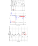
I simulated mutual impedance of two dipole antenna array with fdtd.but I don't know why my
Z12 has a big peak (for example 250 ohms),While in several reference,I saw the peak about 80 ohms.

in my desing:
distance between elements = 0.5λ
dipoles are λ/2.
radius = λ/200

I attached my results.
do you have any idea?do you think my results are true?
z12 of two dipole array.png
 
Last edited:

my dear, i ii like to help but i dont know really the type you are seeking
 

Hi lili
thank you.
my question is not clear?I want to get mutual impedance of two half-wavelength dipole or quarter-wavelength monopole antenna array.
my answer has a big peak in z12.why?
 

Hi lili
thank you.
my question is not clear?I want to get mutual impedance of two half-wavelength dipole or quarter-wavelength monopole antenna array.
my answer has a big peak in z12.why?

i ii ask someone for you.
 

Clarification of terms.

you say "dipoles are λ/2". At which frequency?

How do you measure "mutial impedance" of antennas? In network analysis, mutual impedance involves a driving current source and open circuit voltage measurement, which is hard to implement in RF frequency range.
 

Clarification of terms.

you say "dipoles are λ/2". At which frequency?

How do you measure "mutial impedance" of antennas? In network analysis, mutual impedance involves a driving current source and open circuit voltage measurement, which is hard to implement in RF frequency range.


let me ask someone for you please i forgot its long i have used it. should in case you need loan for you project you can get me informed i know of a comapny that can finance you in any way.
 
Last edited by a moderator:

Hi FvM.
you right.
λ/2 is 60 cm.so I get a frequency range = (20 MHz - 3 GHz).because in my fdtd simulation cell sizes are such that fmax = 3GHz.this is ok.
in fdtd,because we can set voltage source,simpler,So I excited 1st dipole by a voltage source and 2nd dipole is short circuit.
so,I obtain Y parameters and then convert Y to Z parameter.such that:
Z12 = -Y12/(Y11^2 - Y12^2).
elements are similar,So => Y11 = Y22 and also BY RECIPROCITY : Y12 = Y21.

why my z12 has a big peak?it is true?

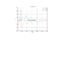
Also,I attached my S parameters results.do you think that my results are true?
MY S PARAMETERS.png
 
Last edited:

The value of about 80 ohms is for a half wave dipole where your change the distance between the dipoles. You keep the distance and antenna length the same, but change frequency.

Your half wave length (60cm) equals 250 MHz, but your peak is around 400 MHz (I guess). So In my opinion you can't refer to values for a half-wave dipole, as at 400 MHz your antennas are closer to full-wave resonance. You may check the impedance curve versus frequency for a single antenna.
 

Hi Wim.
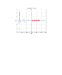
self impedance of excited dipole is true.I attached it:
z11.png
but I don't know peak of z12 is at f=350 MHz.

my program is true.because I have tested it with several papers.
what is your idea about z12?
 

Peaks are expectable because the antenna pair is a resonant structure, alos impedance maximum for the full wave dipol. To determine if the result details are plausible, we have to ask about the simulation setup, particularly size of the simulation space, does it have absorbing surfaces?
 

yes,I used from Pml.
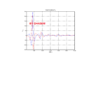
I think that my result is true.because Y21 has a peak at 250MHz exactly (following attachment)
y21.png

I used from following expression to obtain z12:
Z12 = -Y21/(Y11^2 - Y21^2).

but I don't know why in Z12,Peak is at f=350MHz.
do you have any idea?

why full-wave dipole?length of each arm is λ/4 = 30 cm. gap region of each dipole is 1 cm.So I simulated a half-wave dipole!
my Y to Z is not false?because my Y21 is true,as attachment.
 
Last edited:

It is now clear that in your simulation, the high mutual impedance values coincide with full-wave resonance (based on your impedance graphs). It is not strange that the mutual impedance is high as the input impedance of a single antenna is also high, and the antennas are in their main beam of radiation (so there is still energy transfer).

When the electrical length is 2 lambda (also high impedance situation), mutual impedance is no longer high as antenna 1 is no longer in main beam of antenna 2 due to complete other radiation pattern. I know this theory is not real theory as the antennas are still in the transition field zone.
 

Wim,why full-wave resonance?
when you say full-wave,i.e total_length_dipole = lambda.
so because total_length = 1.2 m => lambda = 1.2 meter.
So, resonant_frequency = 3e8/1.2 = 250MHz.

while,in impedance graph,peak is at f=350 MHz.NOW if f_res = 350MHz => lambda = 86 cm => total_lenght/lambda = 1.4

why you say mutual impedance values coincide with full-wave resonance ?
 

Where the dipole impedance is highest (about 650 Ohms in your case), the antenna is electrically in full-wave resonance. See it as a source in between two electrically half-wave long open stubs. You know that the physical length is less then the electrical length due to field fringing and now also feed point capacitance.

If in doubt, look to the current distribution at the frequency where the impedance is highest.
 

my first resonance is at f=250 MHz (see posting#9).
my question is that why Y21 parameter,has a peak at f=250 MHz (according to first resonance point),while Z12 has a peak at f=400 MHz,approximately (according to 2nd resonance point)?
do you think my Z12 is true?how can I give an explanation for this simulation?
 

I have another question.
suppose,we have two simulation (simulation(1) and (2)) that in each of them,we have two dipole antenna array.
if we have:
Y12 in simulation(1) > Y12 in simulation(2)
So,mutual coupling in simulation(1) with respect to simulation (2) is bigger?

- - - Updated - - -

I have another question.
suppose,we have two simulation (simulation(1) and (2)) that in each of them,we have two dipole antenna array.
if we have:
Y12 in simulation(1) > Y12 in simulation(2)
So,mutual coupling in simulation(1) with respect to simulation (2) is bigger?
 

Mutual coupling can be severe. A good test to investigate into this is to put your two dipoles far away (say 10 lamdas), then make the distance smaller and smaller. Check how the S11 and S21 changes. Please keep me updated of your findings.
 

Hi rodgerwxh
if I want to apply your suggestion,I have to run my program for long time.
it is clear that when distance increase,mutual coupling decreases.
do you have any idea about posting # 16?
 

I dare not say anything if I am not 100% clear of the problem. How do you define mutual coupling between two dipole antenna array? If I understand correctly, your model is two dipole antennas right? You only have two ports in total, each dipole antenna has one port right?

If I am correct, then its not "Two dipole antenna array" its two dipole antennas with two ports. Then the mutual coupling can be measured through S21, right? Unless you have different definitions, this is my understanding.
 

what it is difference between "Two dipole antenna array" and "two dipole antennas with two ports"?
an array antenna is a configuration that is designed for specific purpose.you suppose my array is composed from two dipole antenna with distance lambda/2. both have same phase and are similar.so,when you want to measure mutual impedance between them,you have to short circuit one of them and excite other.then you can measure Y21 = I2/V1.
I2 is induced current in dipole(2) and V(1) is excitation voltage in dipole(1).
 

Status
Not open for further replies.

Part and Inventory Search

Welcome to EDABoard.com

Sponsor

Back
Top