Continue to Site

Welcome to EDAboard.com

Welcome to our site! EDAboard.com is an international Electronics Discussion Forum focused on EDA software, circuits, schematics, books, theory, papers, asic, pld, 8051, DSP, Network, RF, Analog Design, PCB, Service Manuals... and a whole lot more! To participate you need to register. Registration is free. Click here to register now.

[Moved]Timed beeper circuit layout

Status
Not open for further replies.

slitza

Newbie level 5
Joined
Jan 9, 2013
Messages
10
Helped
0
Reputation
0
Reaction score
0
Trophy points
1,281
Location
South Africa
Activity points
1,453
Hi Everyone

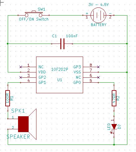
Yesterday upon visiting my (somewhat) local optometrist, I was advised to look up every 5 minutes or my eyes will stay myopic (nearsighted). So I thought of a resolution- I will design and build a 5 minute beeper alarm operated by batteries to remind me to look up every 5 minutes. Here follows a list of components I have thought of introducing:

1. a speaker
2. volume control
3. power on/off switch
4. power cells
5. a timer
6. a led to indicate power on/off

So after writing down my list I realized that what i want to make was not covered in high school electronics- go figure. During my 2 years of compulsory electronics we only made a small pcb that works off a 9V battery with a red and green led that alternates on and off. I still tried designing a circuit with the components. Heck, I even downloaded a pcb design software, drew a circuit, entered values which i understood and believe it or not, but the test run concluded that the design works- however I'm still skeptical and do not believe the circuit design ought to be as simple as i have drawn it. For instance, I have no idea whether the power cells should be a large and expensive 9V battery as opposed to 1 or 2 rechargeable AA's, because I do not know the voltage of the other mentioned components. If only there was a book/website that explain these beginning concerns plain and simply.

I will try attach an image of the circuit layout I designed and I would like as much feedback and suggestions on it as possible- even if it slightly off topic! Also, any suggestions as to brands, component quality and the likes for small projects like this would also be appreciated.

Hope to hear from you all soon ;)
5 minute beeper concept layout.jpg
 

It won't work quite as you drew the diagram because the timer won't run if it has to switch itself on!
Also consider that the LED will drain the battery whenever it is lit so if this has to be switched on for long periods it might be worth looking at a different indication method.
Personally, I would use a small PIC processor for this because it can do everything in one component and has tiny power consumption but the classic method would be to use three timers, one for the 5 minutes between beeps, one to decide how long the beep lasted and one to make the beep itself. If you follow my suggestion you will get the lowest cost and most compact design and it will run on two rechargeable AA cells (even AAA should last for days) but you will have to do a little simple programming to make it work.

I would do it this way - simple PIC (under $1US) flashes LED briefly once per second to show it is switched on, driving a small beeper with say 1KHz bursts of tone for 250mS once every 5 minutes.

Brian.
 

Hi Brian, thank you for replying with such detail- you pretty much convinced me just by me reading your reply. I just started searching for a local electronic component store. There are just a few things i'd like to quote and ask something about.

It won't work quite as you drew the diagram because the timer won't run if it has to switch itself on!

I'm not sure i understand you perfectly... Will it not work because of the position the timer is placed in the current or does it have something to do with the switch being right after the power cell + side? As a side-question, is it better practice then to place switches just before the - pole of a power cell in a closed current?

Also consider that the LED will drain the battery whenever it is lit...

Good point! Thanks for pointing out the severe flaw.

...the classic method would be to use three timers,...

That is interesting- I didn't expect 3 timers would be needed. I'm curious as to what the order of the timer's positions would have to be, but instead I'm following up on the PIC processor you mentioned.

About the PIC processor- does it imply I need to buy a PIC processor component, hook it up to the computer somehow, write the code to execute the 5minute-beeping-procedure (and in which language??) and then just hook the PIC processor up to a beeper and power source? (Also- if it is true that the beeping procedure has to be programmed, can the beeper be programmed what frequency to beep and how many beeps with time-spaces between beeps?)

I would do it this way - simple PIC (under $1US) flashes LED briefly once per second to show it is switched on, driving a small beeper with say 1KHz bursts of tone for 250mS once every 5 minutes.

I barely know anything about PIC components... Could you perhaps suggest a specific bit and pin count and brief explanation why it is best suited?

I do have some experience programming using Delphi 7, so if there is programming involved you just upped my excitement level to do this project!
 

...the classic method would be to use three timers...
Surely this can all be done with two NE555 timer chips, or one NE556 dual-timer?

The first timer generates a quarter-second pulse every 5 minutes. This pulse activates the second timer, which is configured to make the "beep".

The PIC solution may be better for someone who already has experience with PIC programming and has the necessary equipment etc, but otherwise the 555 solution (or similar) should be easier and cheaper.
 

Perhaps I took your schematic too literally. If it was an actual electrical diagram, the current through the speaker would flow through the timer so between beeps, the timer wouldn't run - a chicken and egg situation!
In any serial circuit, you can break the connection with a switch at any point but obviously some places are more convenient and sensible than others.

The three timers are there because you need three different periods for it to work:
1. the timer to set the 5 minutes between beeps
2. the timer that is triggered by timer 1 but runs for say 250mS to set how long the beep sound should last for
3. the timer that produces the high and low signals at 200Hz to drive the speaker. (actually, 200Hz is rather low, 750Hz to 1,500Hz is a better choice)

The beauty of a software solution is you can produce all these timings in a simple program, either using software loops to create the timing delays or using the hardware timers built in to most microcontrollers.

Many cheap processors are available and everyone will tell you their own opinions on which is most suited for the job. I would suggest the PIC10F200 which only has 8 pins and two of those aren't used! You could connect the speaker to one pin through a variable resistor to set the volume and connect the LED and series resistor to another. The switch would just turn the power on and off from the battery. They operate from anthing betwen 2V and 5V so they are ideal for use with two 1.5V cells.

If you can program in Delphi you would have no problem at all with any of the PIC languages. In view of the small amount of memory in the 10F200 which is just 256 bytes, it would be easiest to use assembly language, the programming tools are free but you would need a gadget to store it in the chip itself. Let us know what you think of my suggestions and we can work from there.

Brian.
 

I do have some experience programming using Delphi 7, so if there is programming involved you just upped my excitement level to do this project!
Cool - a fellow programmer.:)
That's a good start, but...
About the PIC processor- does it imply I need to buy a PIC processor component, hook it up to the computer somehow, write the code to execute the 5minute-beeping-procedure....
"hook it up to the computer somehow" is where the problem comes in. You write the code on your PC, but then to download it to the PIC microcontroller you need special hardware - a "PIC programmer", and they're not cheap.

The PIC may only cost $1, but if you have to pay $50 for the programmer then it's not worth it for a one-off project, IMHO. If you're going to make a habit of this, that's a different story though.

- - - Updated - - -

The three timers are there because you need three different periods for it to work:
1. the timer to set the 5 minutes between beeps
2. the timer that is triggered by timer 1 but runs for say 250mS to set how long the beep sound should last for
3. the timer that produces the high and low signals at 200Hz to drive the speaker. (actually, 200Hz is rather low, 750Hz to 1,500Hz is a better choice)
Yes, but the first two can be done with a single timer. The duty cycle just has to be set appropriately - 250mS on, 5 minutes off.

- - - Updated - - -

I was advised to look up every 5 minutes or my eyes will stay myopic (nearsighted). So...
Rethinking the whole thing...

Presumably it's a computer screen you need to look up from. In that case, why not just write some software that beeps the computer's speaker every 5 minutes? That way there's no electronics to build - it's pure programming.
 

Godreyl - you could be right about the 555/556 solution but the on/off ratio of the first timer would be 1200:1 which would be difficult to produce directly although it would be possible with an RC trigger circuit to the second timer. The problem would be the supply voltage, the 555/556 have a 4.5V lowest working voltage and Slitza only has 3V at most and probably less from two rechargeable batteries. The PIC is specified to work down to 2V and experience says they will keep working down to about 1.8V.

A simple PIC can be programmed for much less than $50, although I use more professional equipment myself, there are plenty of easy to build programmers on the Internet. A quick look on Eb*y finds several for under $10.

Brian.
 

Wow, so much information... gotta keep a head (pun intended) here. I havent been able to find any relative easy sources of self-study on electronics so most of the english terms i read i have to look up first. I did a google search of the NE555 and PIC10F200 components and they appear pretty much identical apart from the inscriptions. From the search results which i read, i understood a little more information given on the PIC10F200 so im liking that one right now, except I may have to go with the NE555/NE556 dual-timer because of the PIC programmer hardware (which I am definitely considering if i can get my head around this =D).

the current through the speaker would flow through the timer so between beeps, the timer wouldn't run
Based on the diagram in my first post, would connection a third wire in parallel to the volume control and beeper fix the chicken-egg,egg-chicken ****-up? Im actually glad you took the diagram literal because that was exactly how i thought it could work!

If you can program in Delphi you would have no problem at all with any of the PIC languages. In view of the small amount of memory in the 10F200 which is just 256 bytes, it would be easiest to use assembly language, the programming tools are free but you would need a gadget to store it in the chip itself. Let us know what you think of my suggestions and we can work from there.
I am willing to learn assembly code if it is the code most often (or most preferably) used in PIC programming. On the contrary, I'm starting to think writing the timer's code in delphi will be too big for the chip. Im guessing that both of you, Brian and Godfrey, are able to write code for the PIC's- do you guys use assembly or another low level language when writing code for PIC's?

I am currently studying architecture and it is also a lot of staring at a screen or paper when drawing, so I am guessing I could use the 5-minute-beeper almost around the clock. Furthermore, it would be real wicked to incorporate electronic features into the models i build- led room lights and what have you!

I had a look at the PIC programming hardware on ebay and the cheaper types seem to only be able to program 2 set sizes of chips. Are the more expensive types able to program a wider variety of chips or perhaps just easier means of use?

In your latest post, Brian, you say something very interesting about the voltage difference between the two IC components. Im not currently aware of any rechargeable 9V batteries, but afaik, they tend to last quite long. Im not too concerned about the final price between the two different solutions (excluding the programming hardware), because for now it is more important to learn different methods and good practice.

So, as I understand using either 555 or PIC, the components needed will be power cells, the 555/PIC, the beeper, an optional LED and an optional switch -no more volume control needed when using a fixed frequency beeper. Both methods will require programming (not yet sure if how the code would differ, but for now i hope to just design a proper circuit layout). Does it really boil down to power cell preference? 2xAA's means the PIC or a 9V would mean the 555?
Just did a follow up search on the pin-count of the PIC, and i read wiki says that using PIC is an easy entry level and has a small instruction set to learn- a good start perhaps.
If the PIC has 6 pins labelled a,b,c,d,e,f then
a - power cell entry current from positive pole
b & c - LED power indication if a switch is installed
d & e - beeper in/out respectively
f - power cell exiting current to negative pole

Im thinking that i may be faaaar off the beaten track, because i saw a 555 and pic diagram and there seemed to be specific pins for specific functions.. oh dear
 

The NE555 and PIC10F200 are completely different animals. The NE555 is a dedicated timer IC and can't be used for much else, the PIC is a general purpose microcontroller that can do many jobs depending on the program inside it. In fact it can even emulate an NE555 !

Your diagram was a good idea but not really practical. Even with the extra wire it wouldn't work properly. Nice try though!

Regarding programmng languages. You can't use Delphi to program PICs because it needs the support of Windows and various DLL files, in any case the amount of memory in a PIC wouldn't be sufficient. Even a small Delphi program would be several 10s of Kb and the humble PIC10F200 only has 0.25Kb in total. There are hundreds of PIC types, all optimized for various tasks and with different resources in them, the 10F200 is the smallest of the lot but still very capable. For example I use them to read temperature sensors, format the results and control wireless senders. I use PIC10F202s which are the same chip with 512 bytes of memory in video generator units. When memory is small, it's usually most efficient to use assembly language, when the chip has more than about 2K it starts to be easier to use 'C' as the language. High level languages like C and BASIC need their own housekeeping routines which use up some of the available space whereas assembly language doesn't. There are free assemblers and compilers available at the manufacturers web site.

The PIC10F200 has one ground, one supply and four general purpose pins. Three of these can be inputs or outputs under program control and one is only usable as an input. What I had in mind was to use one pin to drive the LED and one to drive the beeper. The other two can be left unconnected unless you can think of a use for them. The PICs are reprogrammable so if you decide to change it's inner workings all you do is overwrite the original program with a new one so you can adapt it for other uses or add extra features at a later date. I checked the UK price for a single PIC at 44p which is about 6 SA rand so they are not expensive.

You can get rechargeable 9V batteries but being less popular than AA sizes they are considerably more expensive and you might have trouble finding a charger for them too.

The programming unit isn't complicated. I'm not endorsing this particular brand but to see for an idea of it's complexity. With this one you would use connecting wires from the row of pins to the PIC, either on a board in a socket to hook up to it.

Brian.
 

Thanks for clarifying the difference between the units- seems i was completely wrong. I appreciate the descriptions and explanations you provide. Right now assembly language seems like the only way to go and still the preferable language even if you have more than enough memory available on a PIC.

I am currently looking for a local store where i can buy one of these 10f200's and have a look at which programming units are available here. Im not endorsing either, just using the link as an example to my question; the unit i see in https://www.bravekit.com/pic_dip_programmer is about 3x the price of the unit in www.bravekit.com/pic_jdm_icsp_microchip_programmer. How advanced do you need to go in order to use the PIC DIP programmer to the same efficiency as you would using just the PIC JPD programmer?

In the meantime, i will figure out the pic10f200 pin connections and draw up a new diagram. If you say rechargeable 9V batteries are more expensive and chargers for them are rare in the UK, they are most likely not available here at all so im glad to have seen why decisions like this are not somewhat based on preference or whim, but availability.

Off to draw with the new information in mind, cheers! =D
 

You don't need to be advanced at all. The board with all the sockets is just an extension of the pins on the small module or other similar ones. The "icsp" it mentions is "In Circuit Serial Programming" which is what almost all PICs use these days. The only connections to the PIC are ground, supply, VPP, clock and data. To put the program in the chip you power it up, raise the VPP voltage from 5V to 12.5V which puts the PIC into programming mode then clock commands and memory values into the data pin in time with raising and lowering the voltage on the clock pin. All this is done in the programmng software so you don't have to worry about it. Some PICs work without the 12.5V (LVP or Low Voltage Programming) but not the 10F200 and in any case on those devices it ties up an extra pin to select normal or programming mode.

All you need to do is connect the pins on the small board directly to the pins on the PIC, if you have circuit board or protoyping board, just leave the wires attached until you are happy it all works then remove them aftwerwards. The PIC will still work with the programmer attached to it so you can debug/reprogram/test without changing and connections or removing the chip. Often for speed I use a prototyping board to hold the PIC and use jumper wires to connect it to the programming unit like this:

I arrowed a PIC being programmed in the bottom right corner. All those Pro's out there - please don't shoot me, I know the wires are longer than they should be!
Ignore the rest of the stuff, it's a project I'm working on at the moment and it all fits on a small PCB which I'm currently designing.

You might note that I'm not the neatest person inthe World!

Brian.
 

Godreyl....
Hi Brian
You make a number of good points. I didn't realize PIC programming could be done so cheaply. My comments were no doubt also colored by my own bias / personal preference away from PICs. (for me; designing and building circuits is fun, whereas programming is a chore).

I am currently looking for a local store....
RS-online looks good. I haven't bought from them myself yet, as it's been more convenient for me (near Cape Town) to get stuff over the counter from one of the Yebo stores. Yebo's range of goodies has shrunk alarmingly over the last few years though.
 

Thank you for the links godfrey. I visited 1 mall and 2 shopping centres today and there isnt a single store within any of the centres that sell either the microcontrollers or pic programmers.

I checked the yebo online store and there is luckily a branch a few km's from where my father works. Bad thing is that the programmers they sell are so expensive, i could hire someone to design, build, program and deliver it for the same price. Also, i couldnt find any microcontrollers on yebo's site.
RS-online seems to only have 3 pic programmers and these are even more expensive than the one's at Yebo. They do however have the pic10f200 for the approx $1/R7 which is great, but driving out like R80-100 to get there or paying delivery is ridiculous.

I will keep RS-online as a last resort, but for now I'll keep searching for a store. One of the shops i was referred to instead referred me to Game Exchange somewhere in Greenside, so ill give them a call first. Im starting to think it will be easier and cheaper buying a cheapskate or second hand appliance and removing a pic10f200 from it (research to make sure first!). Who knows, there might even be one on the old motherboard in the garage, which im checking next.

There used to be an experilab outlet in Alberton Mall, but they seem to have closed down. The closest 2 experilab outlets are in Pretoria which is is about 80km from here. Experilab used to have a counter where they sold loose electronic components.

When i thought about why it is such a hassle to find a microcontroller seller, i realised that most sales of such components in south africa must be made by large companies and therefore there are no individual outlets for the everyday citizen. Heck at this rate, I might even phone Witwatersrand Uni or Uni of JHB and ask them where their students buy their components!

In the meantime i have spent time reading about microcontrollers- I learned about the 8 bits in a byte, how the programming works through the bits via binary code or hex and the likes. Next step is to research what the abbreviations stand for in Brian's last post and work out how the components for the 5-minute-beeper circuit will connect to the pins named by the abbreviations.

I am also getting concerned about my decision to use a pic10f200, because i havent found a shop selling a pic programmer for under $20 or R200. It will **** having to use yet another whole new approach just because of this.
 

You can pick them up cheap on Eb*y and pay with Paypal but make sure you get the type with pins unless you are good at soldering! Look out for 8 pin DIP packages and not 6 pin surface mount packages.

Likewise, look for programmers that can manage the 10F200 and preferably many other types too! Although the commands for programming PIC devices are different for every device, they almost all follow the same electrical rules so generally you will find the only difference between programmers is in the PC software used to drive them.

Brian.
 

Im so excited this morning- I may have found a electric component retailer about 3-4km from my home! Yesterday on our way back up Voortrekkersweg towards Johannesburg, i noticed a sign K.G.B. Discount Electrical. The sign was far too small to read any details, but googling it this morning i found a possible retailer in a shopping centre right next to one i visited yesterday /facepalm! Unfortunately the website wont open (((kgbelectrical.co.za/)-even adding www. didnt help) im just mentioning and in no way trying to advertise. if anything ill give them a piece of my mind for having a broken website!) Im going to phone the number i found and hear about specifically the 10f series components and a programmer for it- no use buying the chip if i cant find an affordable programmer (perhaps i ought to search a thread of building a programmer).

Currently im still reading about the PIC's and how their pin-connections work. I just went through a description of a 16f84 and understand a bit better how the I/O works.

What i have learned is that my timer-input will be analogue probably, so an A/D converter will be needed (which may be present in the 10f200- i have yet to check). Im not yet sure if an external oscillator will be needed and so far the oscillating frequencies confuse me the most as i cannot match how the pulse frequencies matter i.e. analogue input will need a # MHz oscillator for so-and-so reasons. Im not entirely sure what VPP is. It sounds like it is the input for voltage, but on the 16f84 diagram the voltage input was annotated as VDD.

I will need a power source (1 power), ill have a timer of 5 minutes as input (1 input), ill have a beep as output (1 output). Does that seem closer to right than my previous attempts?
 

You are overcomplicating things!

The clock oscillator is 4MHz but it's actually built inside the chip so you don't have to worry about that. Similarly, the tmer is inside so you don't need to provide any outside signals at all.
If you want to make the timer interval adjustable with a potentiometer thats easy too but as you stated, you have to read the voltage from it somehow and for that you need an ADC. Again, don't panic, almost all the PIC types have at least one ADC inside them. Because it's the very bottom of the range in features, the 10F200 doesn't have one so if you decide to make it adjustable, I would suggest changing to the 12F683 instead. they are almost the same but the 12F683 has extra goodies inside it, including the ADC and some extra timers.

The I/O is actually very easy, there are two registers, one decides whether the pin is an input or an output (TRISx register) and the other is the register that actually writes to the pins or reads from it (PORTx). In most applications you decide the direction based on the circuitry connected to the pin and then leave it that way although you can change direction in mid execution if you want to. The 16F84 is quite good as a 'tutorial' device but is rather dated now, the newer types are cheaper and easier to use. Those acronynms are: VDD = the normal positive supply, VSS = the normal negative supply (usually 'ground') and VPP = the programming voltage. You only use VPP when actually placing the code inside the IC, it activates the internal programmng circuits and changes the pin functions so some become programming inputs. When you remove VPP the chip reverts to normal operation with the new program stored inside it. I should point out that the time taken to program a PIC is very short, it varies according to how much memory is being programmed but for example a 10F200 takes about 3 seconds! I think the slowest I program is the dsPIC33 series which takes about 20 seconds. I wouldn't recommend one of those to a beginner though!!

If you can't get hold of a PIC or a programmer, let me know and I'll see if it's feasible to source from here.

Brian.
 

After the insightful comment that im making it too complicated, i searched google images for small circuits using the pic10f200 and it was quite helpful. Some circuits comprise of nearly only the 10F, power cells, and an output medium. With that in mind, I had a look at the 10F200's datasheet with the pin allocations. From there I drew a new circuit with only the 10F200, power cells and one output medium. I see that pin 1 and 6 are labelled N/C, which i guess means no connection or something and cannot/rarely are used. The VDD was pin 2 and VSS pin 7. GP0-3 are in order 8,4,3,5. GP3 is also the VPP, which thanks to Brian I now know is the pin used for programming.

Also with the new simple circuit, I drew it under the impression that any details such as the time between beeps and the beep frequency/tone will be regulated by the code.

5 minute beeper concept layout with PIC10f200.jpg

I have given the beeper's program algorithm a little thought. The process will be something like
1* run program on power up
2* when 300 seconds are reached, an interrupt signal should pause the timer, the beeper-macro should play and on finish, resume counting where it left off.

I hope the new concept is closer to a working circuit!

Yesterday upon visiting the KGB Electrics, I was referred to AP Electrical. I searched for a website and was glad to find one- until i saw the cheaper PIC programmer for only the 10F series going for R341.60, which translates to $38 at R9/$1. I'm not even entirely sure that im reading the label right, it is called a DIP Adapter for 8-pin 10Fxxx. Compared to the $6 programmer on ebay that you showed me, it would be stupid to spend that much. I have no idea why these programmers are so expensive in South Africa. Most of them cost about 2 playstation 2's worth! Perhaps a chunky old school circuit is the way to go in a 3rd world country?
 

O gosh... was just sitting pondering about the circuit I drew in the my previous post- pin 3 where the speaker is connected may have to additionally connect to the pin 1 wire for power. Think ill start drawing this up on some of the free pcb design software and run a test to see if it works!
 

Sorry - been away in meetings all day and not been on here as frequently as usual.

Your diagram is correct except one side of the speaker can be returned to VSS (negative side of the battery) and you should have a resistor in series with it to limit the volume and also prevent it drawing too much current from the PIC pin. If you want a flashing power indicator you can use one of the other I/O pins to drive an LED, again through a resistor. Although you might get away with it, you should add a capacitor across the VDD and VSS pins close to the PIC as well.
Like this:
3202110400_1358374603.jpg


I would suggest the code follows this flow:
1. Wait 2 seconds
2. Flash LED for 200mS
3. Add 1 to a counter
4. If the counter hasn't reached 1500 (2 x 1500 = 3000 = 5 minutes) go to step 1
5. Beep the speaker for 200mS
6. Reset the counter
7. Go to step 1.

This will briefly flash the LED once every two seconds to let you know it's switched on and running and beep once every 5 minutes.

Brian.
 

Status
Not open for further replies.

Similar threads

Part and Inventory Search

Welcome to EDABoard.com

Sponsor

Back
Top